Power control circuit

A power control and circuit technology, applied in power amplifiers, control/regulation systems, and regulation of electrical variables, etc., can solve the problems of power amplifiers not reaching saturated power output, reducing battery life, etc.

Inactive Publication Date: 2012-02-15
VANCHIP TIANJIN TECH
View PDF5 Cites 18 Cited by
  • Summary
  • Abstract
  • Description
  • Claims
  • Application Information

AI Technical Summary

Problems solved by technology

When low power output is required, high base voltage causes excessive current draw, thus reducing battery life
On th...

Method used


Image

  • Power control circuit
  • Power control circuit
  • Power control circuit

Examples


Embodiment Construction

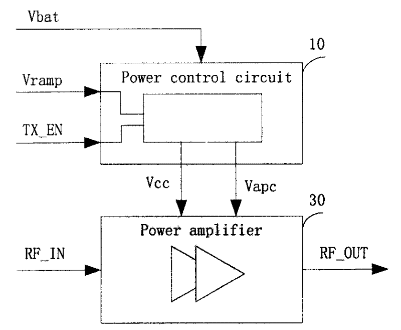
[0009] exist figure 1 Described in is a general power amplifier with a power supply control circuit. A power supply control signal (VRAMP) is generated by the baseband to provide the power amplifier (20) with a power supply voltage. The enable signal TX_EN provides the power on / off control circuit (10). The power amplifier (30) amplifies the radio signal and transmits it through the antenna.

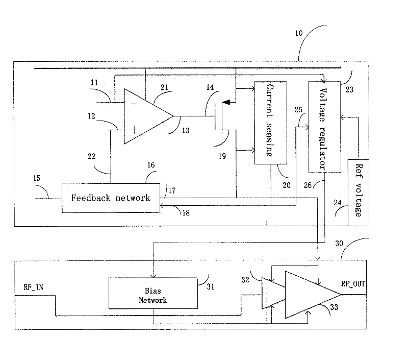
[0010] exist figure 2 The middle power supply control circuit (10) includes an error amplifier (21), a feedback network (16), a pass element (19) and a current detection circuit (20). One node of the feedback network is connected to a fixed voltage. This can be ground (zero) or a non-zero value. Another node (17) is connected to the drain of the pass element (a PMOS transistor). Node (17) is also the output of the power control module. It is usually connected to the collectors of all stages of power amplifiers in the power amplifier (30) module. A current sensing circuit (20) mo...


PUM


Abstract

The invention discloses a power control circuit. The invention relates to control on power of a power amplifier and in particular relates to control on current of a power amplifier under different power requirements. The common power control circuits are only regulated by power control signals generated by basebands and can not optimize the current due to different power requirements, therefore the fixed bias circuits designed to meet the high power requirement can lead to unnecessary current consumption under low power requirement. The invention provides a method for dynamically regulating the current according to difference of the output power of the power amplifier. In principle, the method relates to a system which comprises a power supply control circuit and a power amplifier, wherein the power supply control circuit comprises an error amplifier, two voltage stabilizers and a current detection circuit; the detection circuit detects the current flowing through the power amplifier and generates a detection signal; the signal can be a voltage or a current; in one embodiment, the current flowing through the power amplifier can be copied and reduced to a scale; the copied current is further modulated by an input power control signal and is fed back to the error amplifier; and then the error amplifier generates an output voltage to control a base on the power amplifier, thus achieving the aims of dynamically controlling the base voltage and further optimizing the current. The power control circuit is mainly used for controlling the power of the radio frequency power amplifiers.

Description

Technical field: [0001] The invention relates to the output power control of the power amplifier, in particular to the current control of the power amplifier under different power requirements. Background technique: [0002] The level of power consumption in modern wireless communications is becoming more and more important for mobile phones. A large part of the power consumption of mobile phones is consumed in power amplifiers when transmitting signals through antennas. Therefore, controlling the power consumption of the power amplifier is a very important indicator. [0003] The power consumption control of the power amplifier can be realized by controlling the voltage of its base or collector. A common approach is to fix the base voltage and change the collector voltage to achieve. In order to meet the needs of high power saturated output, the base voltage is usually set higher. When low power output is required, a higher base voltage results in excessive current draw...

Claims


Application Information

Patent Timeline
IPC IPC(8): G05F1/56H03F3/20
Inventor 王峰杜晓航
Owner VANCHIP TIANJIN TECH
Why Eureka
Try Eureka