Three-working-position electric operation mechanism for switching device

A technology of electric operation and switching equipment, which is applied to the power device, electric switch, circuit, etc. inside the switch. It can solve the problems of reduced output angle, heavy manual operation, and large inertia of the transmission system, so as to achieve small output angle error, The effect of easy manual operation and simplified transmission structure

Inactive Publication Date: 2012-02-15
NINGBO XINGBANG ELECTRIC
View PDF5 Cites 31 Cited by
  • Summary
  • Abstract
  • Description
  • Claims
  • Application Information

AI Technical Summary

Problems solved by technology

However, the isolation / grounding switches on the GIS are all rotary inputs, and the linear output mechanism needs a set of conversion device to change it into a rotary motion before it can be used, and the structure is complicated.
[0007] ④Motor / cylindrical gear pair / incomplete gear transmission pair / locking arc positioning output rotary motion, it is a single motor, incomplete gear transmission is prone to undercutting and acceleration mutations, in order to ensure reliable motion, there is a gap between the locking arcs The gap increases the range of angle changes in three positions, and the accuracy is low
[0013] 1. When the motor starts and stops, the inertia of the transmission system is not fully considered, and it is impossible to realize the three-station electric operation of fast closing, opening and grounding
The inertia of the transmission system is too large, so that the output angle is inaccurate, the mechanical limit pin is damaged, and the switch body is damaged, or the internal parts of the mechanism are collided and deformed, shortening the service life
[0014] 2. Insufficient consideration of the degree of harm and preventive measures for the damage of the travel limit switch or the ineffectiveness of the function
If the above mechanism is driven by a sheave and locks the positioning of the arc plate, if the travel switch in the middle position is in poor contact or does not work or is damaged, the middle position will not stop, and it will be directly closed by the isolation switch to the ground switch or from the ground. The switch closes to the isolating switch closes, causing the switchgear control system to be disordered
If the travel limit switch is damaged or does not work in the isolation closing position or the grounding closing position, the motor will be burned or the mechanical limit will be deformed or broken, causing the main contact of the switch to over-position and damage the main switch. dangerous
[0015] 3. Insufficient consideration of the change of output angle and position due to the weight of the load
If the load is light, the output angle will increase; if the load is heavy, the output angle will decrease, so the contacts of the isolation or grounding switch cannot meet the technical requirements of the opening distance and contact stroke
[0016] 4. The transmission system is not self-locking, the deformation of the mechanism during the transmission process, the reaction force or the electric repulsion generated by the main contact, make the output shaft move in the opposite direction, and the output angle decreases
[0017] 5. Manual operation is heavy
[0018] 6. The manual operation interlock function is not complete. The manual operation of the isolating switch and the grounding switch is not an independent operation hole. It has no mechanical relationship with the switch state, and there is no mechanical interlock with other switching elements, which is prone to misoperation.

Method used


Image

  • Three-working-position electric operation mechanism for switching device
  • Three-working-position electric operation mechanism for switching device
  • Three-working-position electric operation mechanism for switching device

Examples


Embodiment Construction

[0051] The specific implementation manners of the present invention will be further described in detail below in conjunction with the accompanying drawings and embodiments. The following examples are used to illustrate the present invention, but are not intended to limit the scope of the present invention.

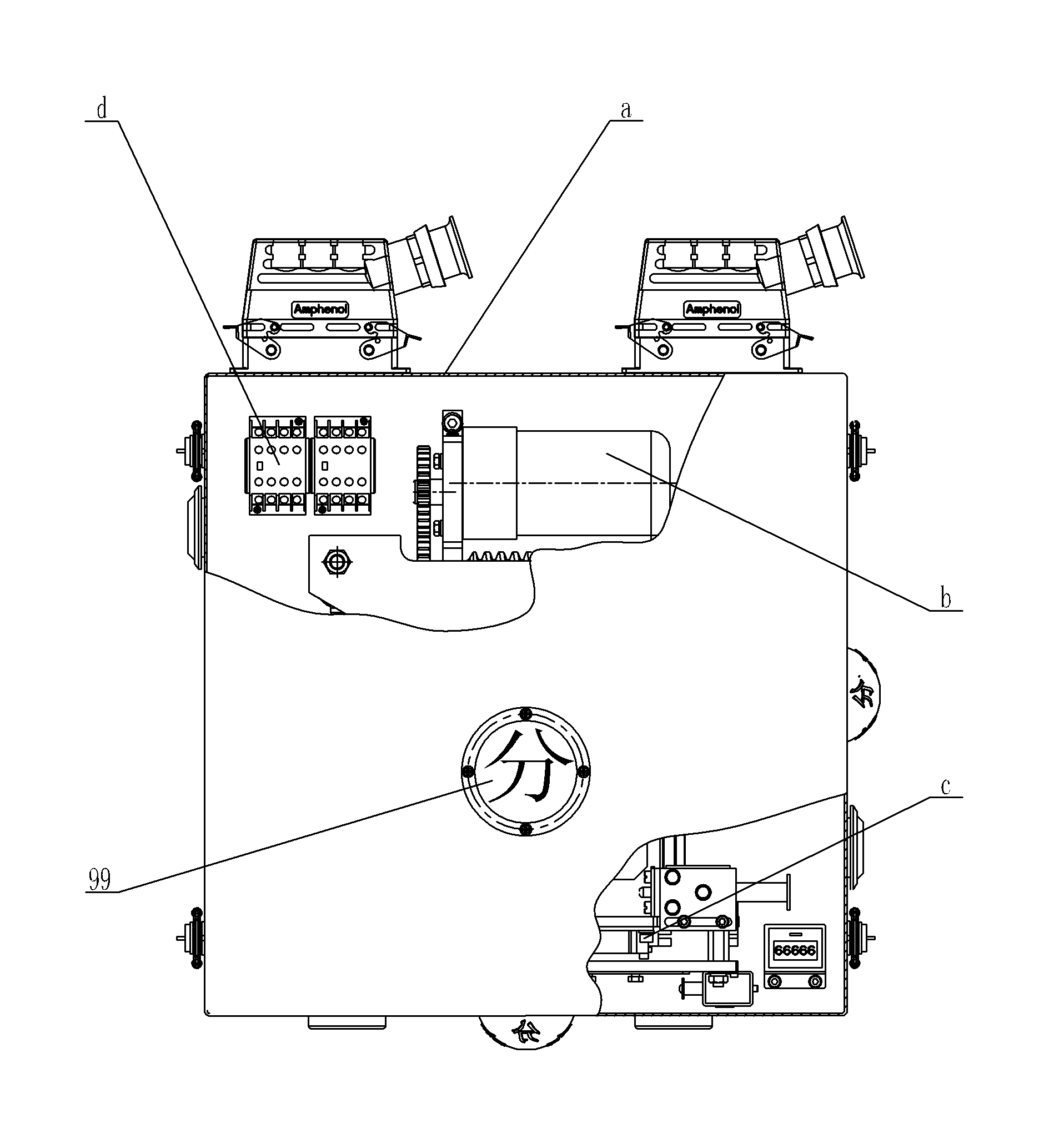
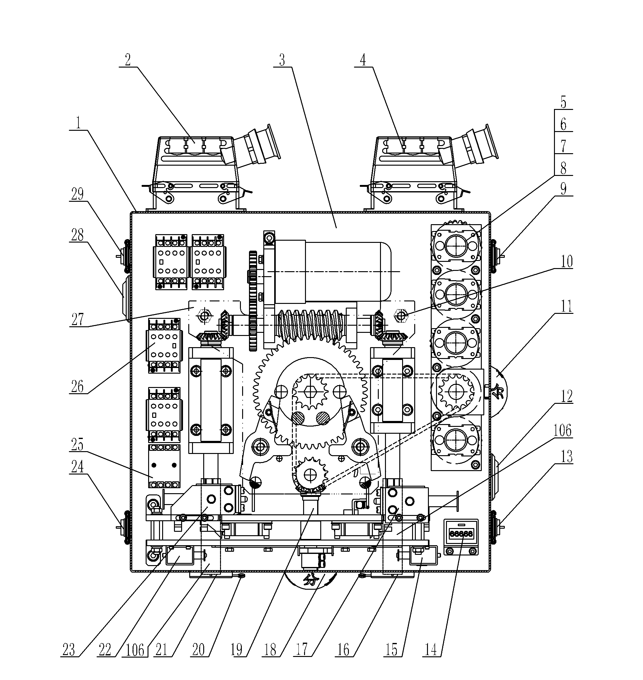
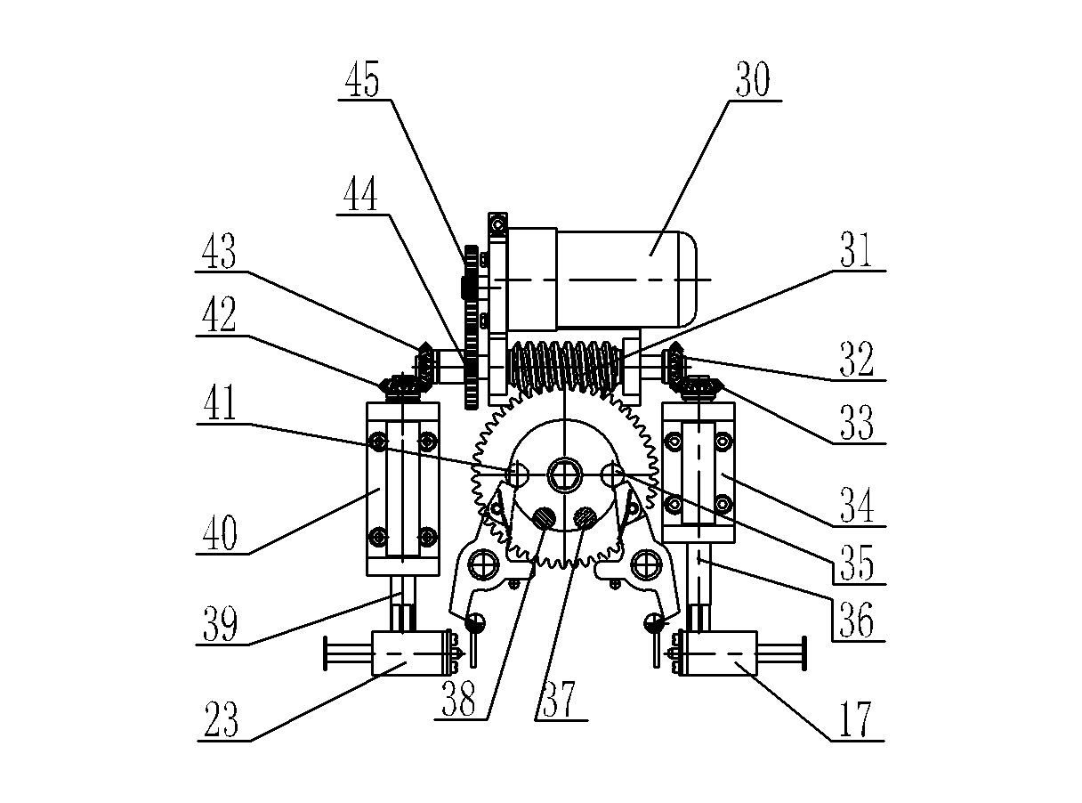
[0052] In this embodiment, the output shaft of the mechanism turns, and the manual operation panel is set as the front view direction, and the output shaft is below the chassis, looking down from top to bottom: counterclockwise is close-open-ground, clockwise is ground-open-close; it can also be on the contrary.

[0053] Such as figure 1 , figure 2 , image 3 , Figure 4 , Figure 5 , Figure 6 , Figure 7 , Figure 8 Shown:

[0054] The three-position electric operating mechanism for switchgear is composed of four parts: chassis assembly a, driving device b, manual interlocking device c, and electrical control device d. The driving device b, the manual interloc...


PUM


Abstract

The invention discloses a three-working-position electric operation mechanism for a switching device, and a driving device, a manual interlocking device and an electrical control device are arranged in a case of the mechanism, wherein the driving device adopts a single motor, a gear pair, a worm and worm gear pair, a two-way controllable overrunning clutch and an output shaft and is connected with a three-position isolation/grounding switch through a shaft coupling so as to realize the operations of closing, opening and grounding; a frame is provided with position-limiting clutch pin shafts in the closing position and the grounding position respectively, and a pair of detents, a half shaft and a tripping electromagnet are arranged in the opening position of the frame, thereby realizing the positioning for closing, opening and grounding and the mechanical clutch protection; a chain wheel transmission/bevel gear pair is used for realizing the state indication of the three positions on the front surface and the side surfaces and the position switching of a three-working-position auxiliary switch; and the manual interlocking device can realize manual-electrical interlocking and electromagnetic interlocking among switching elements. The three-working-position electric operation mechanism is simple in structure, stable in output angle, accurate in positions and unrelated to the inertia of a system, the mechanical-electrical interlocking is realized between isolation and grounding, the production and the use are safe, the reliability is very high, the cost is low, and the operations of closing a break and opening the break can be performed rapidly.

Description

technical field [0001] The invention relates to the field of electric operating mechanisms, in particular to an electric operating mechanism for three-position isolating / grounding switch operations in gas-insulated metal-enclosed switchgear (GIS). Background technique [0002] In recent years, with the continuous advancement of high-voltage switchgear technology, gas-insulated metal-enclosed switchgear has developed in the direction of miniaturization, compounding, multi-functionalization of components, and intelligentization. The disconnector (DS) and the earthing switch (ES) are combined into three The station isolating / grounding switch (DES) can save the electrical operation interlock and realize natural mechanical interlock without various misoperations between DS and ES. In this way, it is necessary to use an electric operating mechanism to realize the conversion between the three stations: DS closing position (isolating switch closed + grounding switch open), ES closin...

Claims


Application Information

Patent Timeline
Patent Type & Authority Applications(China)
IPC IPC(8): H01H9/20H01H3/26
Inventor 王蒲全曹化磊
Owner NINGBO XINGBANG ELECTRIC
Why Eureka
Try Eureka