Injection mould device with spray nozzle self-centering device

An automatic centering and injection mold technology, which is applied in the field of hot runner injection molds, can solve the problems of long installation time, time required for alignment and debugging, high requirements for workers' operation proficiency, and difficulty in correct installation, so as to simplify assembly work, The effect of shortening the assembly cycle and reducing the installation time

Active Publication Date: 2012-02-22
哈希斯热流道科技(苏州)有限公司
View PDF5 Cites 0 Cited by
  • Summary
  • Abstract
  • Description
  • Claims
  • Application Information

AI Technical Summary

Problems solved by technology

Such a mold structure requires all parts to be assembled sequentially at the installation site of the hot runner injection mold. It takes a long time to align and debug the center of the nozzle a

Method used


Image

  • Injection mould device with spray nozzle self-centering device
  • Injection mould device with spray nozzle self-centering device
  • Injection mould device with spray nozzle self-centering device

Examples


Example Embodiment

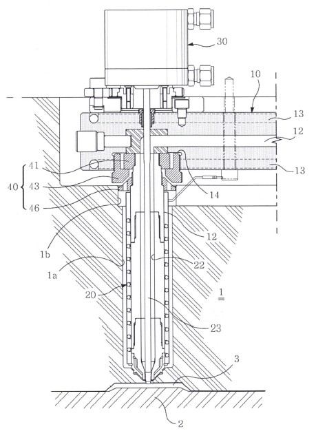
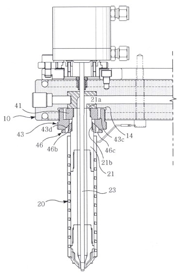
[0024] Example 1: see figure 1 As shown, an injection mold equipped with an automatic nozzle centering device includes a fixed mold 1, a movable mold 2, a mold row cavity 3 between the fixed mold 1 and the movable mold 2, and is provided in the fixed mold 1. The upper manifold 10 is provided with one or more resin supply channels 12 through which molten resin supplied from the outside can pass, and the molten resin passing through the resin supply channel 12 is maintained at an appropriate temperature and arranged on the resin supply A plurality of heating wire rods 13 around the channel 12; a nozzle device 20 that selectively supplies the molten resin through the resin supply channel 12 to the mold row cavity 3 is installed in the nozzle installation hole 1a of the fixed mold 1.

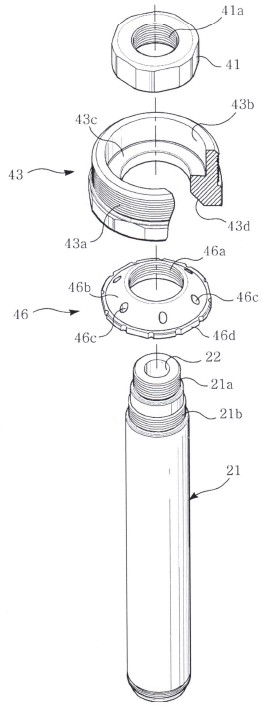
[0025] Such as Figure 1~2 As shown, the nozzle device 20 includes a nozzle body 21 with a resin channel 22 inside. The nozzle valve needle 23 in the resin channel 22 opens the outlet of the resin chan...


PUM


Abstract

The invention discloses an injection mould with a spray nozzle self-centering device. The injection mould with the spray nozzle self-centering device comprises a fixed mould, a moving mould, a mould line cavity, a flow distribution plate and a spray nozzle device, wherein the spray nozzle self-centering device is arranged at the upper end of the spray nozzle device; the spray nozzle self-centering device comprises a connecting part, a protective ring, and a guide ring part which are arranged outside a spray nozzle main body from the top to the bottom; and the spray nozzle main body is fixed to the bottom surface of the flow distribution plate axially through the connecting part by the protective ring. By rotating the guide ring part forwards or reversely, a first central guide surface and a second central guide surface are matched and then are separated to finish the self-centering of the spray nozzle device and keep the centers of related components aligned. A radial sliding clearance is formed between the protective ring and the connecting part to counteract horizontal movement of the protective ring caused by thermal expansion of the flow distribution plate, wherein the bottom surfaces of the protective ring and the connecting part are in sliding contact, so that the spray nozzle main body cannot be influenced by the thermal expansion and deformation and a centering state is remained.

Description

Technical field [0001] The invention relates to a hot runner injection mold, in particular to an injection mold with an automatic nozzle centering device. Background technique [0002] The current hot runner injection mold includes a fixed mold, a movable mold, and a mold cavity between the movable and fixed molds. A manifold is arranged above the fixed mold, and the manifold is provided to heat the molten resin supplied by the main runner. A resin supply channel that passes through when it reaches a certain temperature; the fixed mold is also provided with a valve nozzle device that selectively supplies the molten resin flowing through the resin supply channel to the mold row cavity, and the valve nozzle device The upper end part is embedded in the bottom surface of the distributor plate and the lower end part is fixed in the fixed mold. The nozzle device includes a nozzle body with a resin channel inside and communicating with the resin supply channel and the mold cavity. A he...

Claims


Application Information

Patent Timeline
IPC IPC(8): B29C45/26
CPCB29C45/2725B29C45/2806B29C2045/2729
Inventor 许南旭
Owner 哈希斯热流道科技(苏州)有限公司
Why Eureka
Try Eureka