Hydraulic braking system of container front crane

A technology of hydraulic braking and reach stacker, applied in hydraulic braking transmission device, foot start device, etc., can solve the problems of brake life influence, failure, unstable braking torque, etc., to avoid pressure fluctuation and brake failure, The effect of high work efficiency and novel structure

Active Publication Date: 2012-02-22
WEIHAI HHH MACHANICAL & ELECTRICAL
View PDF9 Cites 4 Cited by
  • Summary
  • Abstract
  • Description
  • Claims
  • Application Information

AI Technical Summary

Problems solved by technology

The hydraulic braking system of the front axle and rear axle is composed of left pedal valve, right pedal valve, accumulator, front axle brake and rear axle brake, and the hydraulic pump fills the accumulator through the filling valve. , the accumulator provides a relatively stable hydraulic oil source for vehicle braking, and is respectively connected to the left pedal valve and the right pedal valve through pipeline connections, and then connects the oil outlet of the left pedal valve to the right pedal valve. The oil outlets of the pedal valve are connected in parallel to the brakes of the front axle and the rear axle respectively through the shuttle valve. There is a pressure switch on the pedal valve, and the pressure switch is connected with the safety warning light. When the left pedal valve or the right pedal When one of the pedal valves of the valve has pressure oil output, it will lead this pressure to the brake to realize the braking function. The disadvantages of this hydraulic brake system are: First, the left pedal valve of this brake system Both the left and right pedal valves use single-circuit braking. If the front axle or the rear axle fails, the braking system of the whole vehicle will fail, which is prone to accidents and has low safety. The second is: due to the left pedal valve and the right The pedal valve brakes the front axle and the rear axle in the same way. The hydraulic control method is used to cut off the clutch. It cannot guarantee whether the vehicle will cut off the power first or generate the brake first, which will have a great impact on the life of the brake. The third is: During emergency braking, step on the left and right pedal valves at the same time. If the pedal force on the left pedal valve and the right pedal valve are different, since the oil pressure is generated by comparing the shuttle valve, the pressure is likely to fluctuate and the brake Unstable dynamic torque

Method used


Image

  • Hydraulic braking system of container front crane
  • Hydraulic braking system of container front crane
  • Hydraulic braking system of container front crane

Examples


Embodiment Construction

[0014] Below in conjunction with accompanying drawing, the present invention is further described:

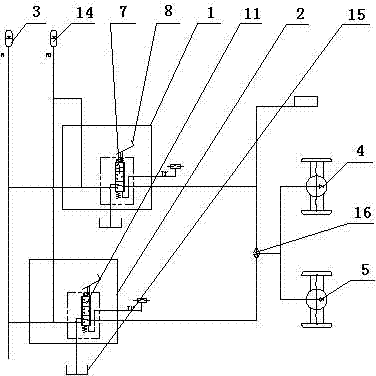
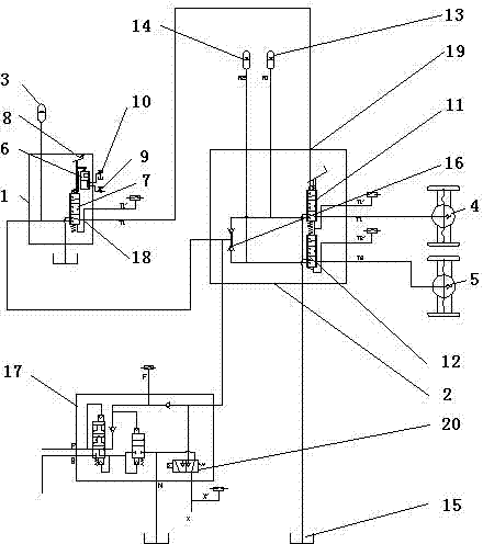
[0015] As shown in the accompanying drawings, a hydraulic braking system for container reach stackers is provided with a car body, and the car body is provided with a left foot pedal valve 1, a right foot pedal valve 2, a liquid filling valve 17, an accumulator 3, The front axle brake 4 and the rear axle brake 5 are characterized in that the right pedal valve 2 is formed by connecting the front axle brake oil circuit and the rear axle brake oil circuit in parallel, and the front axle brake oil circuit and the rear axle brake oil circuit are connected in parallel. Pedal valve brake spools 11 and 12 are respectively arranged on the road, and the oil outlet of one brake spool 11 is connected with the front axle brake 4, and the oil outlet of the other brake spool 12 is connected with the rear axle brake 5. The oil inlets of the two spools are respectively provided with accumulator...


PUM


Abstract

The invention relates to the technical field of container front cranes, in particular to a hydraulic braking system of a container front crane. The hydraulic braking system is provided with a vehicle body, wherein a left pedal plate valve, a right pedal plate valve, a liquid charging valve, energy accumulators, a front-axle brake and a rear-axle brake are arranged on the vehicle body. The hydraulic braking system is characterized in that: the right pedal plate valve is formed by connecting a front-axle braking oil-way and a rear-axle braking oil-way in parallel; a slow-action valve is arranged on the left pedal plate valve; a valve core of the slow-action valve is connected with a valve core of a braking valve in series; the upper end of the valve core of the slow-action valve is connected with pedals; an oil inlet of the slow-action valve is communicated with a variable control port of a variable pump; an oil return port of the slow-action valve is communicated with an oil storage tank; when the left pedal plate valve is pedaled, oil at a braking port of the left pedal plate valve is communicated to a hydraulic control port of the right pedal plate valve, equivalently, the left pedal plate valve has a power cutoff effect at the same time of pedaling the right pedal plate valve. An oil outlet of the liquid charging valve is respectively connected with the energy accumulators of a parking braking valve, the left pedal plate valve and the right pedal plate valve, and the parking braking valve is integrated on the liquid charging valve. The hydraulic braking system disclosed by the invention has the advantages of novel structure, high safety, braking stability and the like.

Description

technical field [0001] The invention relates to the technical field of container front stackers, in particular to a container front stacker hydraulic braking system for lifting and transporting containers. Background technique [0002] At present, the container reach stacker is a professional mobile lifting equipment used for container stacking or docks, railways and other places. Compared with forklifts, the reach stacker is more stable, flexible in operation, and has a higher number of stacking layers. The hydraulic braking system of the front axle and rear axle is composed of left pedal valve, right pedal valve, accumulator, front axle brake and rear axle brake, and the hydraulic pump fills the accumulator through the filling valve. , the accumulator provides a relatively stable hydraulic oil source for vehicle braking, and is respectively connected to the left pedal valve and the right pedal valve through pipeline connections, and then connects the oil outlet of the left...

Claims


Application Information

Patent Timeline
Patent Type & Authority Applications(China)
IPC IPC(8): B60T11/10B60T7/06
Inventor 高立军宗胜利
Owner WEIHAI HHH MACHANICAL & ELECTRICAL
Why Eureka
Try Eureka