Indication control method of automobile fuel gauge

A technology of automobile fuel gauge and control method, which is applied in the direction of volume indication and recording equipment, and can solve problems such as inaccurate indication values

Inactive Publication Date: 2012-02-22
ANHUI JIANGHUAI AUTOMOBILE GRP CORP LTD
View PDF3 Cites 23 Cited by
  • Summary
  • Abstract
  • Description
  • Claims
  • Application Information

AI Technical Summary

Problems solved by technology

[0010] The purpose of the present invention is to solve the problem that the indication...

Method used


Image

  • Indication control method of automobile fuel gauge
  • Indication control method of automobile fuel gauge
  • Indication control method of automobile fuel gauge

Examples


Embodiment Construction

[0031] The present invention will be further described below in conjunction with the accompanying drawings and embodiments.

[0032] The principle of automobile fuel indicator system

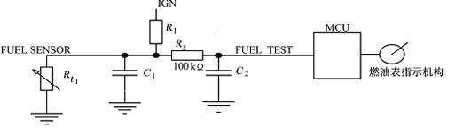
[0033] figure 1 Schematic diagram of an automotive fuel indicator system. The changing resistance signal of the fuel sensor is connected to the fuel test port of the fuel gauge, and the sampling circuit of the fuel gauge converts the changing resistance into a changing voltage by providing a pull-up voltage to the fuel sensor. The changed voltage signal is input to the A / D (analog-to-digital conversion) port of the microprocessor of the fuel gauge and converted into a digital sampling signal. The microprocessor controls the movement of the stepping motor according to the change of the input fuel signal through the preset system software. Mode and speed, so as to drive the pointer of the fuel gauge to indicate the correct fuel position.

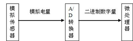
[0034] Fuel signal acquisition

[0035] 2.1 A / D ...


PUM


Abstract

The invention provides an indication control method of an automobile fuel gauge. By adopting tactics including time-division sampling, threshold value control, indicator angle memory, resistance memory, indicator response time control and the like, accurate sampling and stable indication are realized under the condition of specific road conditions or automobile conditions, such as continuous ignition, signal mutation or losing, rapid acceleration, upslope and down-slope and the like; and the problem of abnormal indication in the actual use process of a plurality of the fuel gauges is solved, so that the product performance and the use effect all meet the standard requirements of the automobile industry.

Description

technical field [0001] The invention belongs to the technical field of automobile electronics, and in particular relates to an automobile fuel indication control method. Background technique [0002] The automobile fuel gauge is a device to realize the correct and stable indication of the fuel volume of the automobile fuel tank under different working conditions. At present, with the development of electronic technology, automotive instrumentation is also widely implemented by electronic technology. Due to the imperfect signal processing and control methods of electronic fuel gauges, there are many problems in the actual use of fuel gauges, such as: [0003] (1) The position of the fuel indicator is inconsistent when the continuous ignition is started; [0004] (2) When the signal changes sharply, the pointer will swing; [0005] (3) Control of the pointer running speed when the ignition is started and when the car is powered on and refueled; [0006] (4) The ignition is...

Claims


Application Information

Patent Timeline
IPC IPC(8): G01F15/06
Inventor 彭璐
Owner ANHUI JIANGHUAI AUTOMOBILE GRP CORP LTD
Why Eureka
Try Eureka