Multifunctional metallic phase sample inlaying machine

A technology of metallographic samples and mounting machines, which is applied in the preparation of test samples, etc., can solve the problems of high labor intensity and power consumption, and achieve the effect of improving production efficiency

Inactive Publication Date: 2012-02-22
HEILONGJIANG JIANLONG IRON & STEEL
View PDF0 Cites 10 Cited by
  • Summary
  • Abstract
  • Description
  • Claims
  • Application Information

AI Technical Summary

Problems solved by technology

[0003] The purpose of the present invention is to solve the problem that the existing sample mounting machine can only press one sample at a time because there is only one mold cavity; manual pressurization has the problems of labor consumption and labor intensity, and provides a multifunctional gold phas

Method used


Image

  • Multifunctional metallic phase sample inlaying machine
  • Multifunctional metallic phase sample inlaying machine
  • Multifunctional metallic phase sample inlaying machine

Examples


specific Embodiment approach 1

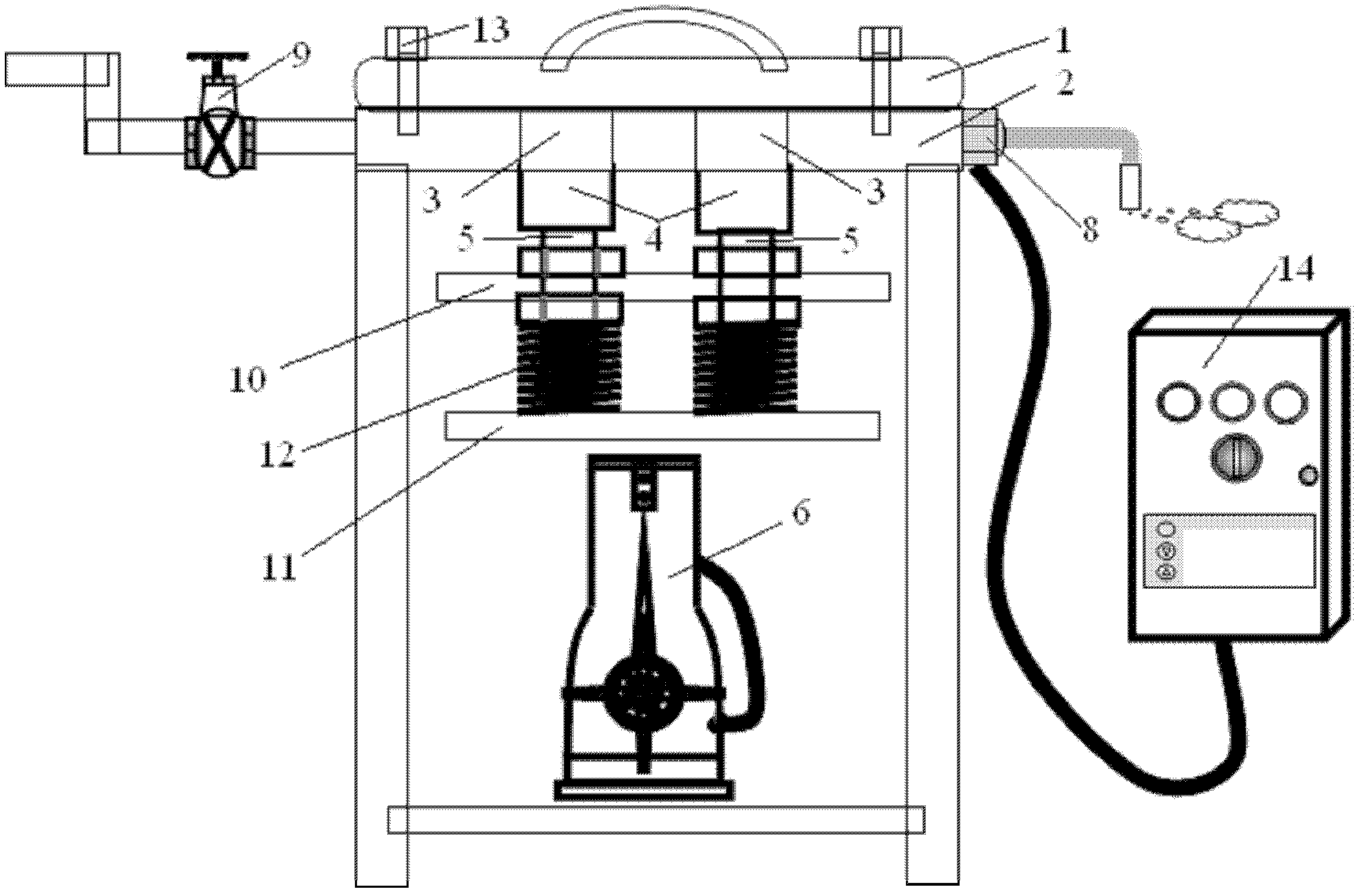
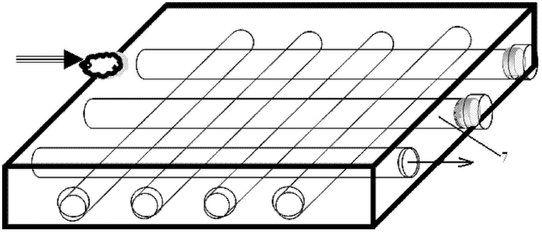
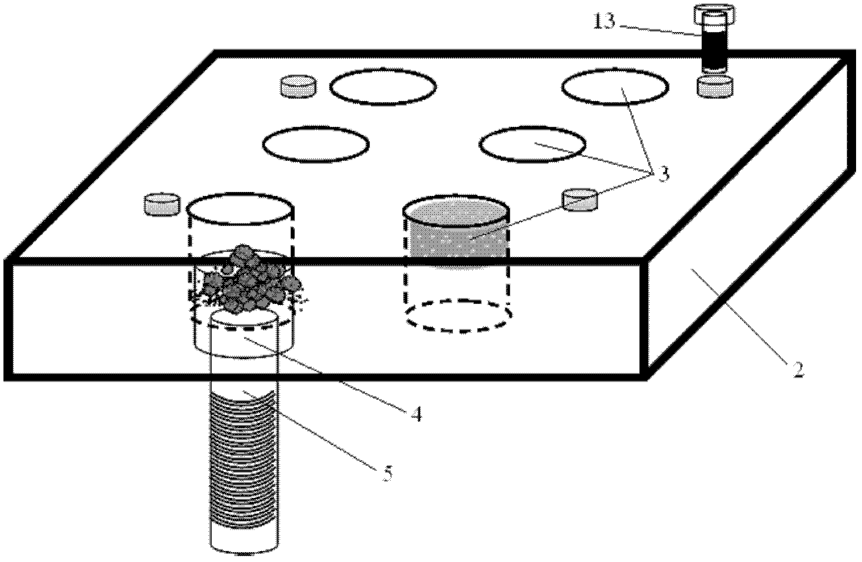
[0007] Specific implementation mode one: combine figure 1 , figure 2 and image 3 Describe this embodiment, which includes a gland plate 1, a steel plate mold 2, six mold cavities 3, a plurality of plugs 4, a plurality of adjusting screws 5, a jack 6, a plurality of steam heating pipes 7, a temperature sensor 8, The heating control valve 9, the No. 1 pallet 10 and the temperature control box 14, the gland plate 1 is fixed on the upper surface of the steel plate mold 2, and a plurality of steam heating pipes 7 are arranged in an orthogonal network inside the steel plate mold 2. There are six transparent mold cavities 3 evenly opened on 2, and each screw plug 4 corresponds to a mold cavity 3 from the lower part of the steel plate mold 2 into the inner cavity of the mold cavity 3, and each screw plug 4 is correspondingly fixed on an adjusting screw 5, the lower ends of all adjustment screws 5 are fixed on the No. 1 pallet 10, and the No. 1 pallet 10 is fixed on the upper surfa...

specific Embodiment approach 2

[0009] Specific implementation mode two: combination figure 1 Describe this embodiment, the difference between this embodiment and specific embodiment 1 is that it also includes No. 2 pallet 11 and a plurality of adjustment springs 12, No. 2 pallet 11 is located between the hydraulic tappet of jack 6 and No. 1 pallet 10 Between, a plurality of adjustment springs 12 are located between the No. 2 pallet 11 and the No. 1 pallet 10, the upper ends of the plurality of adjustment springs 12 are respectively fixed on the lower surface of the No. 1 pallet 10, and the lower ends of the plurality of adjustment springs 12 are respectively It is fixed on the upper surface of No. 2 pallet 11. Other components and connections are the same as those in Embodiment 1.

[0010] A plurality of adjustment springs 12 are compressed after the force applied by the jack, and a plurality of adjustment springs 12 release potential energy in the later stage of coal sample forming, so as to ensure that t...

specific Embodiment approach 3

[0011] Specific implementation mode three: combination figure 1 This embodiment is described. The difference between this embodiment and the first embodiment is that it further includes four fixing screws 13 , and the four fixing screws 13 are distributed at the four corners of the gland plate 1 . Other components and connections are the same as those in Embodiment 1.

[0012] The four fixing screws 13 are used to fix the gland plate 1 to ensure the realization of the required pressure of the coal material and ensure that the gland plate 1 does not deform under high temperature and high pressure.


PUM


Abstract

The invention provides a multifunctional metallic phase sample inlaying machine, relating to a sample inlaying machine, which solves the problems that the existing sample inlaying machine has only one die cavity to press only one sample each time, and manual pressurizing wastes physical strength and has great labor intensity. The sample inlaying machine comprises a pressure cover board, a steel plate die, six die cavities, a plurality of plugs, a plurality of adjusting screw rods, a jack, a plurality of stem heating pipes, a temperature sensor, a heating control valve, No.1 support plate and a temperature control box; the pressure cover board is fixed on the steel plate die; the steam heating pipes are orthogonally arranged in the internal part of the steel plate die in a mesh shape; the six penetrating die cavities are uniformly arranged on the steel plate die; the plugs are arranged in the internal cavities of the die cavities; the plugs are fixed on the upper ends of the adjusting screw rods; the lower ends of the adjusting screw rods are fixed on the No.1 support plate; the No.1 support plate is fixed on the upper surface of a hydraulic tappet of the jack; the temperature sensor is arranged in the steel plate die; the steam heating pipes are communicated with a steam pipeline through a heating control valve; and the temperature sensor is connected with the temperature control box. The sample inlaying machine is used for manufacturing coal-rock analyzing sample.

Description

technical field [0001] The invention relates to a multifunctional metallographic sample inlay machine. Background technique [0002] The existing sample mounting machine is mainly used to fully bond the coal sample and the mounting material into a coal rock analysis sample preparation at a certain temperature. Since there is only one mold cavity, only one sample can be pressed at a time; manual pressure is used, and there is The problem of labor-intensive and labor-intensive. Contents of the invention [0003] The purpose of the present invention is to solve the problem that the existing sample mounting machine can only press one sample at a time because there is only one cavity; manual pressurization has the problems of labor-intensive and labor-intensive, and provides a multifunctional gold Phase sample mounting machine. [0004] Multifunctional metallographic sample mounting machine, which includes gland plate, steel plate mold, six mold cavities, multiple plugs, mult...

Claims


Application Information

Patent Timeline
IPC IPC(8): G01N1/36G01N1/44
Inventor 王宇光王淑菊张勇
Owner HEILONGJIANG JIANLONG IRON & STEEL
Why Eureka
Try Eureka