Rapid prototyping device for special-shaped sheet metal parts

A technology for forming devices and sheet metal parts, which is applied in the direction of forming tools, metal processing equipment, manufacturing tools, etc., can solve the problems of poor sheet metal forming quality and high manual labor intensity, and achieve low processing efficiency, reduce labor intensity, and improve The effect on labor productivity

Pending Publication Date: 2017-11-24
郑州郑飞机电技术有限责任公司
View PDF6 Cites 5 Cited by
  • Summary
  • Abstract
  • Description
  • Claims
  • Application Information

AI Technical Summary

Problems solved by technology

[0004] The purpose of the present invention is to provide a rapid prototyping device for special-shaped sheet metal parts in order to solve the technical problems of poor quality of sheet metal forming and high labor intensity.

Method used


Image

  • Rapid prototyping device for special-shaped sheet metal parts
  • Rapid prototyping device for special-shaped sheet metal parts
  • Rapid prototyping device for special-shaped sheet metal parts

Examples


Embodiment 1

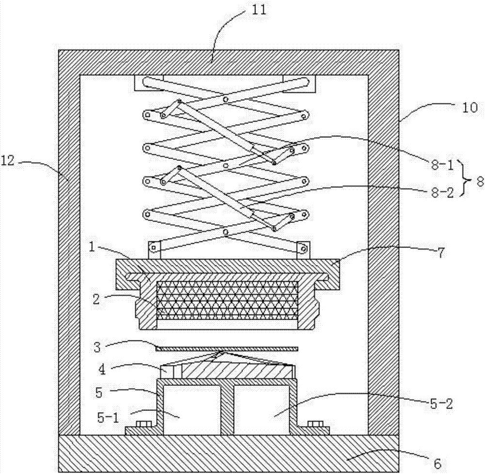
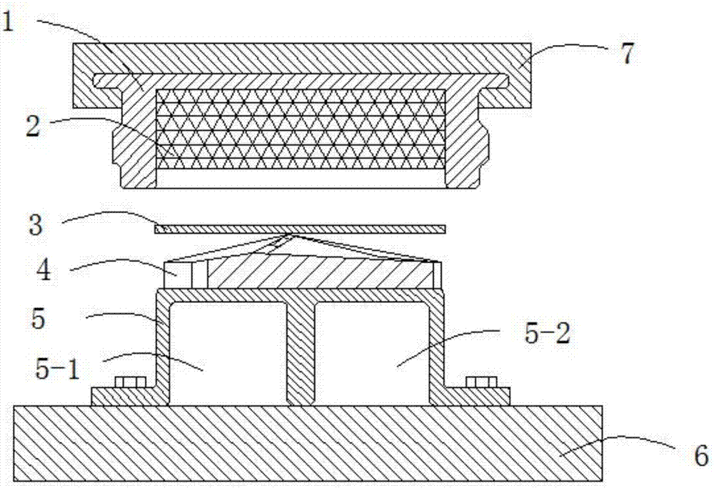
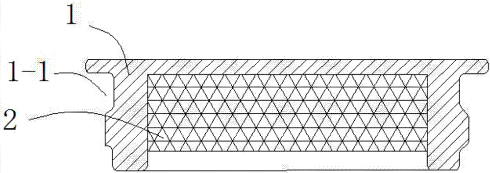
[0025] like Figures 1 to 3 As shown, this embodiment provides a rapid prototyping device for special-shaped sheet metal parts, including an upper mold base 7, a die 1 clamped in the upper mold base 7, a lower mold base 6, and a die base fixed on the lower mold base 6 and the die 1 A matching forming support punch 5, characterized in that the concave mold 1 is a semi-closed cavity concave mold, a rubber plate 2 is arranged in the semi-closed cavity of the concave mold 1, and the thickness of the rubber plate 2 is smaller than that of the semi-closed cavity The depth of the molding support punch 5 is fixedly provided with a molded workpiece film tire 4 for supporting the workpiece 3 to be processed, and the upper mold base 7 is provided with a pressure type lifting mechanism.

[0026] In this embodiment, the mold structure is simple, the processing efficiency can be improved, and the production time can be greatly saved. The most important thing is that the device can be insta...

Embodiment 2

[0028] This embodiment is further optimized on the basis of embodiment 1, specifically:

[0029] The pressure-type lifting mechanism includes a left vertical support plate 12 and a right vertical support plate 10 installed at the left and right ends of the lower mold base 6, and a connecting horizontal support plate 12 and the right vertical support plate 10 are connected between the left vertical support plate 12 and the right vertical support plate 10 The plate 11 is connected with a lifting assembly 8 under the horizontal plate 11. The lower end of the lifting assembly 8 is connected with the upper end of the upper mold base 7, and the lifting assembly 8 is a cutting-type lifting mechanism.

[0030] The lifting assembly 8 includes a scissors support 8-1 and a plurality of hydraulic cylinders 8-2 installed on the scissors support 8-1.

[0031] The scissors support 8-1 includes a plurality of X-shaped scissors connected end-to-end from top to bottom, two adjacent X-shaped sci...

Embodiment 3

[0034] This embodiment is further optimized on the basis of embodiment 1 or 2, specifically:

[0035] The forming support punch 5 is provided with a weight reducing chamber A5-1 and a weight reducing chamber B5-2.

[0036] The sum of the maximum thickness of the molded workpiece film tire 4 and the thickness of the rubber plate 2 is less than the depth of the semi-closed cavity.

[0037] The left and right sides of the upper end of the concave die 1 are provided with clamping grooves 1-1.


PUM


Abstract

The invention discloses a rapid prototyping device for special-shaped sheet metal parts, and relates to rapid prototyping equipment for sheet metal parts. The rapid prototyping device comprises an upper die base, a concave die which is clamped inside the upper die base, a lower die base, a forming support terrace die which is fixed on the lower die base and matched with the concave die, the concave die is a concave die with a semi-closed cavity, a rubber plate is arranged inside the concave die with the semi-closed cavity, the thickness of the rubber plate is less than the depth of the semi-closed cavity, a forming workpiece feta membrane for supporting a workpiece to be machined is fixedly arranged on the forming support terrace die, and a pressure elevating mechanism is connected to the upper die base. According to the rapid prototyping device for special-shaped sheet metal parts, the surfaces of the obtained parts are smooth and flat, and the defects of indentation, scratches and convex-concave shapes appearing on the surfaces of the parts when the traditional methods are used for forming the parts are resolved.

Description

technical field [0001] The invention relates to rapid prototyping equipment for sheet metal parts, in particular to a rapid prototyping device for special-shaped sheet metal parts. Background technique [0002] Sheet metal forming is to apply external force to metal wool such as thin plates, thin-walled profiles and thin-walled pipes to cause plastic deformation or shearing, so as to become a part processing method with expected shape and performance. [0003] In the existing sheet metal forming process, many parts with special-shaped surfaces need to use mold tires when forming, and they are repeatedly corrected on the mold tires by manual beating. The part surface after processing in this way leaves traces left when beating, and the part surface is uneven, and the surface quality is poor; and the labor intensity of the workman is also very large. Contents of the invention [0004] The purpose of the present invention is to provide a rapid prototyping device for special-...

Claims


Application Information

Patent Timeline
Patent Type & Authority Applications(China)
IPC IPC(8): B21D37/10
CPCB21D37/10
Inventor 隗仁轩刘志刚
Owner 郑州郑飞机电技术有限责任公司
Why Eureka
Try Eureka