Backing distance measuring method and device, and backing radar

A technology of reversing radar and distance, which is applied in the field of testing reversing distance and reversing radar, and can solve the problem that the sensitivity of reversing radar cannot be adjusted.

Active Publication Date: 2013-05-15
SHENZHEN LONGHORN AUTOMOTIVE ELECTRONICS EQUIPCO
View PDF7 Cites 0 Cited by
  • Summary
  • Abstract
  • Description
  • Claims
  • Application Information

AI Technical Summary

Problems solved by technology

[0004] The purpose of the embodiment of the present invention is to provide a method for testing the reversing distance, aiming at solving the problem that the sensitivity of the existing reversing radar cannot be adjusted

Method used


Image

  • Backing distance measuring method and device, and backing radar
  • Backing distance measuring method and device, and backing radar

Examples


Embodiment 1

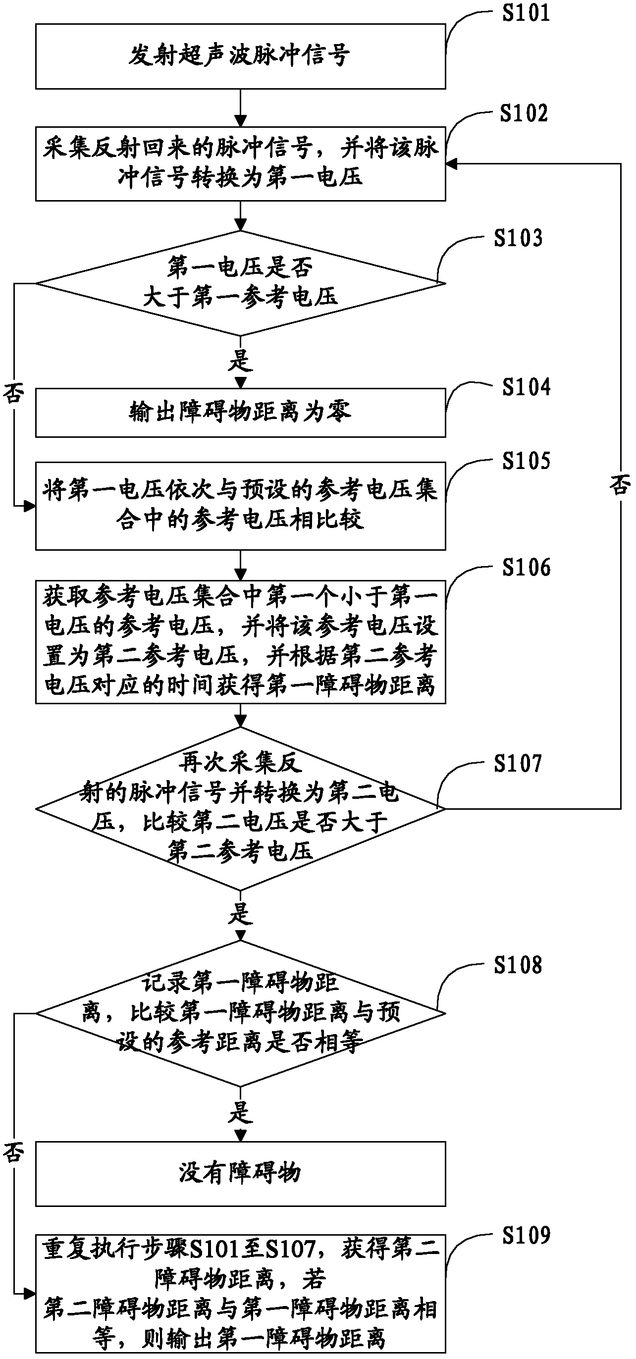
[0042] Such as figure 1 Shown is a flow chart of the method for testing the backing distance provided by the present invention. For ease of description, only the parts related to the embodiment of the present invention are shown.

[0043] In step S101, an ultrasonic pulse signal is transmitted.

[0044] In the embodiment of the present invention, the ultrasonic probe is activated by the single chip microcomputer to transmit the ultrasonic signal. Depending on the probe, a different number of ultrasonic pulses can be emitted. For example: if 10 or 12 pulses are transmitted, for an ultrasonic wave with a frequency of 40KHZ, the period of each pulse is 25us.

[0045] In step S102, collect the reflected pulse signal, and convert the pulse signal into a first voltage.

[0046] In the embodiment of the present invention, when the transmitted pulse signal encounters an obstacle and is reflected back, the reflected pulse signal is collected, and the pulse signal is converted into t...

Embodiment 2

[0072] In order to obtain the final obstacle distance more accurately, in the second embodiment of the present invention, multiple probes are set to test the obstacle distance multiple times.

[0073] Specifically, after the other probes are used to transmit ultrasonic pulse signals respectively, the method from step S101 to step S106 is executed to acquire distances of multiple obstacles, and the minimum value of the distances of these obstacles tested is taken as the final result. Wherein, the number of probes may be 4, 6 and so on. The number of probes is equal to the number of calculated obstacle distances.

[0074] In the embodiment of the present invention, since multiple probes test the obstacle distance separately to obtain multiple obstacle distances, and finally take the minimum value of the measured obstacle distance, the final obstacle distance result is more accurate and noise is prevented. and other false detections of interference signals.

Embodiment 3

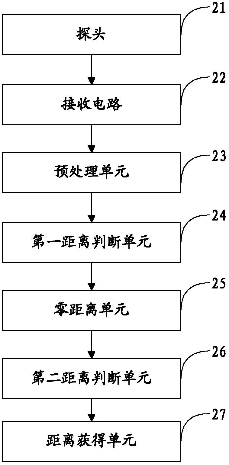
[0076] figure 2 The structure of the device for testing the reversing distance provided by the embodiment of the present invention is shown. For the convenience of description, only the parts related to the embodiment of the present invention are shown. The device can be a software unit, a hardware unit or a combination of software and hardware built into the reversing radar, or it can be integrated into the reversing radar or the application system of the reversing radar as an independent pendant. in:

[0077] The probe 21 is used for transmitting ultrasonic pulse signals.

[0078] In an embodiment of the invention, there are multiple probes 21 .

[0079] The receiving circuit 22 is configured to collect the reflected pulse signal and convert the pulse signal into a first voltage.

[0080] The pre-processing unit 23 is configured to amplify, filter, and voltage double and detect the first voltage, and perform AD conversion on the first voltage.

[0081] The first distanc...


PUM


Abstract

The invention provides a backing distance measuring method, a backing distance measuring device and a backing radar, which are suitable for the field of application of automobiles. The method comprises the following steps of: emitting an ultrasonic pulse signal by using a probe; acquiring a reflected pulse signal, and converting the pulse signal into first voltage; comparing the first voltage with preset first reference voltage; when the first voltage is not higher than the first reference voltage, comparing the first voltage with reference voltages in a preset reference voltage set sequentially, wherein the reference voltage set is a set of a group of reference voltages of which the voltage values are decreased sequentially and is relevant to pulse propagation time respectively; and acquiring a first reference voltage which is less than the first voltage from the reference voltage set, setting the reference voltage to be a second reference voltage, and acquiring a first obstruction distance according to time corresponding to the second reference voltage. The sensitivity of the backing radar can be flexibly changed.

Description

technical field [0001] The invention belongs to the field of automobile applications, and in particular relates to a method and device for testing the reversing distance and a reversing radar. Background technique [0002] In the existing reversing radar, when testing the reversing distance, only a reference voltage is set to judge the distance of obstacles. When the value of the reference voltage is large, it is difficult to detect obstacles far away, that is, it is not sensitive; and when the value of the reference voltage is small, although obstacles near the distance are easy to detect, they are also insensitive. It is easy to cause false alarms due to the detection of "pseudo" obstacles such as the ground, that is, the sensitivity is too high. [0003] Therefore, the sensitivity of the existing parking radar is determined and cannot be adjusted as required. Contents of the invention [0004] The purpose of the embodiments of the present invention is to provide a met...

Claims


Application Information

Patent Timeline
Patent Type & Authority Patents(China)
IPC IPC(8): G01S15/08
Inventor 李周张猛
Owner SHENZHEN LONGHORN AUTOMOTIVE ELECTRONICS EQUIPCO
Why Eureka
Try Eureka