
Method, system and terminal equipment for mobile payment

A technology of mobile payment and payer, applied in the field of Internet payment, can solve the problems of low security, increased hardware, high cost, etc., and achieve the effect of high transaction efficiency, strong scalability, and low cost

Inactive Publication Date: 2012-02-22
SHENZHEN TEMOBI SCI &TECH
View PDF3 Cites 27 Cited by
  • Summary
  • Abstract
  • Description
  • Claims
  • Application Information

AI Technical Summary

Problems solved by technology

[0003] The purpose of the embodiments of the present invention is to propose a mobile payment method, system and terminal equipment, aiming to solve the problem of payment through the Internet or mobile Internet in the prior art, transaction data is easily intercepted, stolen, tampered, and the security is low ; Payment through WIFI, Bluetooth and infrared rays is inefficient, and payment through radio frequency technology requires additional hardware on existing mobile terminals, high cost, and technical problems that are difficult to promote

Method used


Image

  • Method, system and terminal equipment for mobile payment
  • Method, system and terminal equipment for mobile payment
  • Method, system and terminal equipment for mobile payment

Examples


Embodiment 1

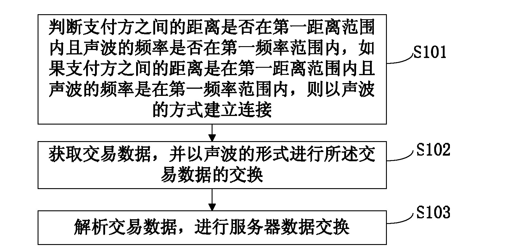
[0023] figure 1 A flowchart of a mobile payment method according to an embodiment of the present invention. Described method comprises the following steps:

[0024] S101, determine whether the distance between the payers is within the first distance range and whether the frequency of the sound wave is within the first frequency range, if the distance between the payers is within the first distance range and the frequency of the sound wave is within the first In the frequency range, the connection is established by means of sound waves;

[0025] The first distance range described in this step can be 10-15 centimeters; the first frequency range can be 1-10 KHz (the sound intensity is within 0.5-1.0 decibels), then the distance between the devices of the payer should be kept at 10 Within the range of ~15 cm, and the frequency of the sound wave is limited to the range of 1 ~ 10KHz, to ensure the safe and effective distance transmission of the sound wave and prevent data from bei...

Embodiment 2

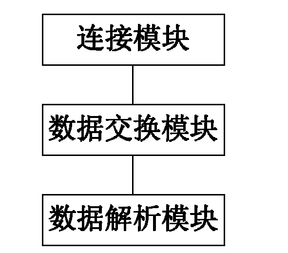
[0054] figure 2 It is a schematic structural diagram of a first preferred embodiment of a mobile payment system according to an embodiment of the present invention.

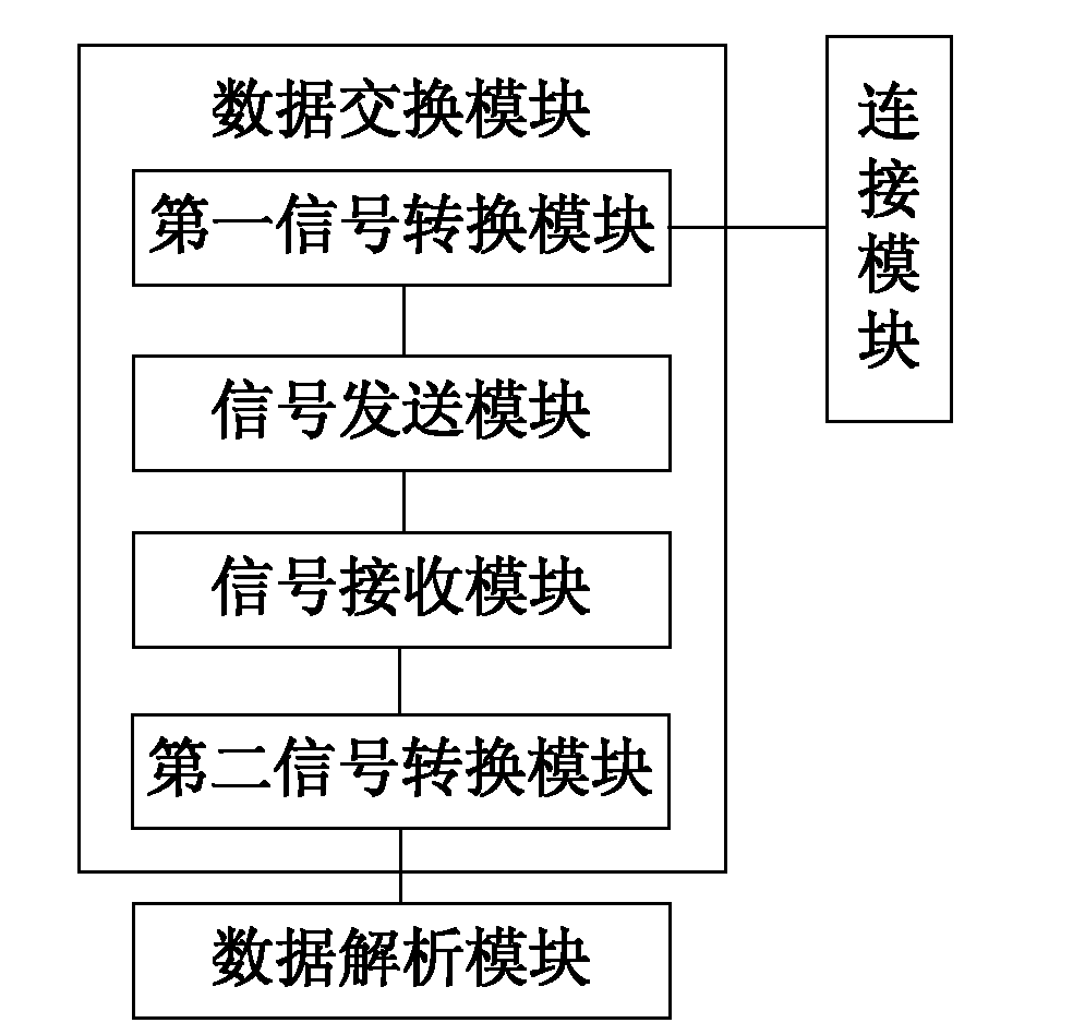
[0055] The system includes a connection module, a data exchange module and a data analysis module;

[0056] The connection module is connected with the data exchange module and is used to judge whether the distance between the payers is within the first distance range and whether the frequency of the sound wave is within the first frequency range, if the distance between the payers is within the first distance range within the distance range and the frequency of the sound wave is within the first frequency range, the connection is established in the form of sound waves;

[0057] The first distance range may be 10-15 centimeters; the first frequency range may be 1-10 KHz (the sound intensity is within 0.5-1.0 decibels), then the distance between the devices of the payer should be kept at 10-15 centimeters Withi...


PUM


Abstract

The invention discloses a method, a system and terminal equipment for mobile payment. According to the method, the system and the terminal equipment, the transaction is safe by controlling the payer distance and sound wave frequency, the possibility that transaction data is intercepted, stolen and tampered is reduced, the transaction efficiency is high, and the transaction data is transmitted in a form of sound waves. Especially, the sound waves are transmitted by using loudspeakers and microphones on terminal equipment, hardware equipment is not required to be modified or increased, the expansibility is high, transplantation is easy to perform, low end mobile phones are compatible, the cost is low, the transaction is safe by controlling the distance and the frequency, the possibility that the transaction data is intercepted, stolen and tampered is reduced, the transaction efficiency is high.

Description

technical field [0001] The present invention relates to the field of Internet payment, in particular to a mobile payment method, system and terminal equipment. Background technique [0002] At present, there are more and more electronic terminal devices in people's hands, and the hardware performance is becoming more and more powerful, and the functions are also increasing. There are also many methods of data exchange between devices. (Wireless Fidelity, wireless compatibility certification), Bluetooth, infrared methods and other data exchange methods, but for private data exchange, there are constraints in terms of data security, efficiency, and existing equipment transformation. For this reason, many enterprises, institutions or individuals are now researching some technical methods that are safer, easier, and do not require modification of existing equipment. NFC (Near Field Communication, short-distance wireless communication technology) technology, which has gradually ...

Claims


Application Information

Patent Timeline
IPC IPC(8): G06Q20/00
Inventor 程举栋
Owner SHENZHEN TEMOBI SCI &TECH
Learn More