
High-voltage vacuum circuit breaker

A vacuum circuit breaker, high-voltage technology, applied in the direction of high-voltage air circuit breakers, high-voltage/high-current switches, circuits, etc., can solve the problem that non-professionals cannot debug, overhaul, drive system power dissipation is too large, and drive system design Complications and other issues, to achieve the effect of improving practical value, good anti-aging performance, and realizing waste utilization

Inactive Publication Date: 2013-08-21
四川奇通电气成套设备有限公司 +1
View PDF3 Cites 0 Cited by
  • Summary
  • Abstract
  • Description
  • Claims
  • Application Information

AI Technical Summary

Problems solved by technology

[0004] (1) The arc extinguishing chamber and the built-in current transformer use silicone oil and desiccant to prevent condensation. Although the O-ring is used for sealing, the aging and thermal expansion of the equipment will still cause the silicone oil to overflow and cause environmental pollution. ;
[0005] (2) The buffer limit device is designed at the center of the lower outlet seat of each phase of the circuit breaker, which makes debugging and maintenance very troublesome, and non-professionals cannot perform debugging and maintenance; in addition, the setting of the buffer limit device makes the The internal space becomes quite narrow, which can easily cause arc flash at the inlet and outlet ends of the current transformer, which will affect the measurement accuracy; at the same time, the arc flash at the inlet and outlet ends of the current transformer will easily cause safety accidents, and make the opening rebound difficult. Stability, which ultimately affects the performance of the circuit breaker;
[0006] (3) CT19, CT10 and CD10 mechanisms are generally used as the power source for the operating mechanism of the circuit breaker, which complicates the design of the transmission system and makes the mechanism very bloated; moreover, the power dissipation of the above-mentioned transmission system is too large, which is not conducive to Practical Applications of Circuit Breakers

Method used


Image

  • High-voltage vacuum circuit breaker
  • High-voltage vacuum circuit breaker
  • High-voltage vacuum circuit breaker

Examples


Embodiment

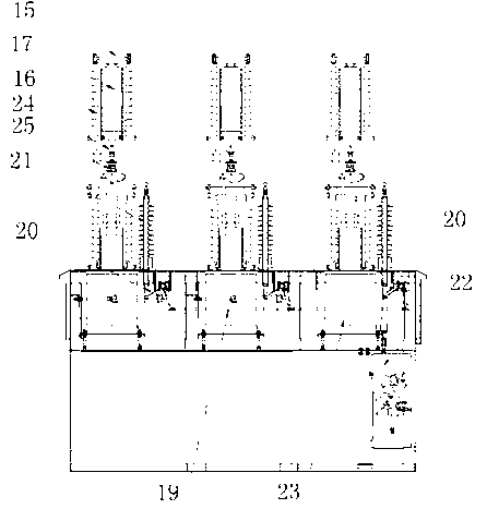
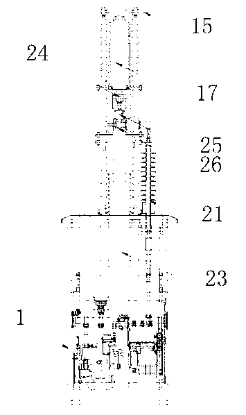
[0042] like figure 1 and figure 2 As shown, the high-voltage vacuum circuit breaker mainly includes the operating mechanism, the current transformer system installed above the operating mechanism, the vacuum interrupter unit located above the current transformer system, and the vacuum interrupter unit and the current transformer. The supporting mechanism used to support the vacuum interrupter unit between the vacuum interrupter systems, and the transmission mechanism connecting the operating mechanism and the current transformer system.

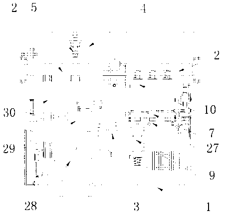
[0043] In the above structure, the operating mechanism such as image 3 As shown, its overall structure includes a mechanism box 1, a main shaft 2 installed inside the mechanism box 1, a kneeling buffer limit device, a closing system, an opening system, a power unit and an energy storage spring 3.

[0044] Among them, such as Figure 4 , Figure 5 As shown, the kneeling buffer limit device includes a buffer 5 installed on the main shaft 2,...


PUM


Abstract

The invention discloses a high-voltage vacuum circuit breaker, which belongs to switchgear in the technical field of electrics, and comprises an operating mechanism, a current transformer system, a vacuum arc extinguish chamber unit, a support mechanism and a transmission mechanism, wherein the current transformer system is arranged above the operating mechanism; the vacuum arc extinguish chamberunit is located above the current transformer system; the support mechanism is located between the vacuum arc extinguish chamber unit and the current transformer system and is used for supporting thevacuum arc extinguish chamber unit; and the transmission mechanism is connected with the operating mechanism and the current transformer system. In the high-voltage vacuum circuit breaker disclosed by the invention, through improving the vacuum arc extinguish chamber unit, a separating brake system, a kneeing buffer inhibiting device and the transmission mechanism, the safety and the reliability of a system are effectively improved, and further, the practical value of a vacuum arc extinguish chamber is greatly improved.

Description

technical field [0001] The invention relates to a circuit breaker, in particular to a high-voltage vacuum circuit breaker. Background technique [0002] Vacuum circuit breaker is one of the common switchgears in electrical system. Its structure mainly includes operating mechanism, arc extinguishing chamber unit with built-in current transformer and transmission mechanism. , compact structure, can quickly and effectively control the on-off characteristics of the electrical system, so it is widely used in various high-voltage electrical systems. [0003] However, there are still many defects in the existing high-voltage vacuum circuit breaker, the main defects are: [0004] (1) The arc extinguishing chamber and the built-in current transformer use silicone oil and desiccant to prevent condensation. Although the O-ring is used for sealing, the aging and thermal expansion of the equipment will still cause the silicone oil to overflow and cause environmental pollution. ; ...

Claims


Application Information

Patent Timeline
Patent Type & Authority Patents(China)
IPC IPC(8): H01H33/66H01H33/666
Inventor 王德华
Owner 四川奇通电气成套设备有限公司
Features
  • Generate Ideas
  • Intellectual Property
  • Life Sciences
  • Materials
  • Tech Scout
  • Unparalleled Data Quality
  • Higher Quality Content
  • 60% Fewer Hallucinations
Learn More