

Blow molding device and blow molding method for plastic fuel tank
A blow molding device and fuel tank technology, applied in the blow molding field of blow molding devices and plastic fuel tanks, can solve the problem that the plasticizing amount of the extruder is not stable enough, the parison cutting is wrinkled, and it is easy to stick together again, etc. problems, to achieve the effect of saving time, reducing maintenance time, and improving appearance quality
- Summary
- Abstract
- Description
- Claims
- Application Information
AI Technical Summary
Problems solved by technology
Method used
Image

Examples
Embodiment Construction
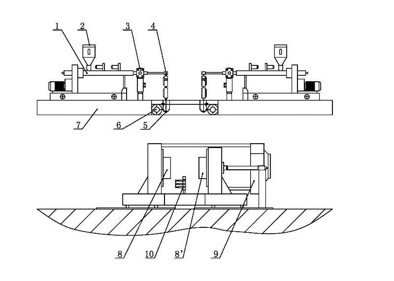
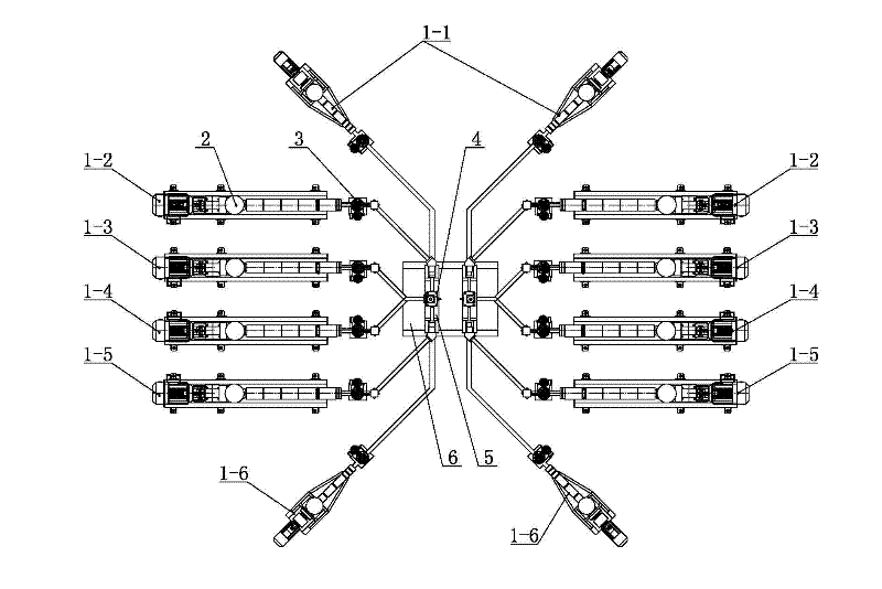
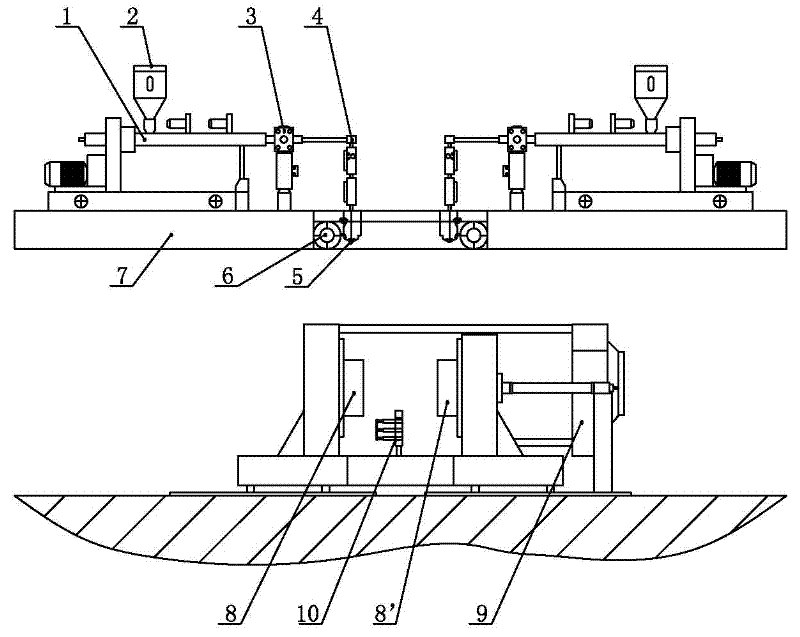
[0022] Such as figure 1 and figure 2As shown, below the supporting platform 7 of the blow molding device of the plastic fuel tank of the present invention, there are fuel tank left half mold 8, fuel tank right half mold 8', mold locking mechanism 9 and fuel tank built-in mechanism 10, fuel tank left half mold or fuel tank right half mold. There are 900 vacuum holes on each mold half; two sets of parison extrusion devices are symmetrically arranged on the support platform, and each set of parison extrusion devices includes extruder 1, hopper 2, melt metering pump 3, compound distribution device 4 and servo flat die head 5; each set of parison extrusion device has six extruders, followed by inner layer high density polyethylene extruder 1-1, inner layer adhesive extruder 1- 2. Barrier material extruder 1-3, outer layer adhesive material extruder 1-4, recycled material extruder 1-5 and outer layer high-density polyethylene extruder 1-6, six The hoppers 2 are respectively insta...
PUM
 Abstract
Description
Claims
Application Information