
Self compensation floating swing arm independent suspension system

An independent suspension and self-compensation technology, applied in the interconnection system, suspension, elastic suspension, etc., can solve difficult vehicle handling, stability, comfort and safety, large frictional resistance between sleeve kingpins, The anti-roll effect is not obvious, etc., to achieve ideal stability, no impact on suspension performance, and ideal comfort

Active Publication Date: 2014-08-06
侯贺
View PDF7 Cites 0 Cited by
  • Summary
  • Abstract
  • Description
  • Claims
  • Application Information

AI Technical Summary

Problems solved by technology

[0006] The structure of the candle suspension has a big disadvantage: that is, the lateral force when the car is running will all be borne by the kingpin sleeved on the kingpin sleeve, resulting in increased friction resistance between the kingpins of the sleeve and serious wear
The main advantage of the multi-link suspension system is that the wheelbase and toe-in change are very small when the wheels jump, and the car can be turned smoothly according to the driver's intention regardless of whether the car is driving or braking. Shaft oscillation at high speed
It has two shortcomings, one is that the anti-roll effect is not obvious, and the other is that it partially offsets the advantages of independent suspension. Even when the vehicle does not turn, when one wheel jumps, the torsion bar will also drive the other side wheel to jump together.
The anti-roll bar connects the wheels on both sides, sacrificing the performance of the independent suspension in exchange for a limited anti-roll effect. If you don't get rid of this method, you won't have an ideal suspension device, and it will be difficult to make the vehicle's handling and stability Ideal for performance, comfort and safety

Method used


Image

  • Self compensation floating swing arm independent suspension system
  • Self compensation floating swing arm independent suspension system
  • Self compensation floating swing arm independent suspension system

Examples


Embodiment 1

[0062] Basic type, such as Figure 9, single group, horizontally placed, composed of floating swing arm (405), compensation mechanism (400), steering knuckle (410), and positioning shock absorber (411), the structure is the simplest, and the basic performance fully meets the requirements. performance, the swing arm can be widened or directly designed as an A shape to increase strength.

Embodiment 2

[0064] commonly used, such as Figure 10 The two sets of devices are distributed at 90 degrees, and the force is reasonable and the structure is relatively simple. The vertical swing arm (405) and compensator (400) only bear the tension when braking or when the wheel encounters resistance, so it can be smaller. to reduce mass

Embodiment 3

[0066] flexible arrangement, such as Figure 11 , installed in any direction perpendicular to the plane of the car body, similar to the basic type.


PUM


Abstract

The invention provides a self-compensating floating swing arm independent suspension system. Including: self-compensating floating swing arm independent suspension device and centrifugal force control scissor type anti-roll bar device two major mechanisms. The two mechanisms can be used together or used alone. Suitable for both front and rear wheels. Realized that on various roads, the vehicle is in various states such as low speed, high speed, and turning, and the wheels always run in a straight line along the vertical direction of the vehicle body, so that the contact area between the tire and the ground is the largest, the kingpin inclination angle, the wheel front Beam, camber, wheelbase, wheelbase and other parameters remain unchanged from the original set parameters; at the same time, when the vehicle is turning, the centrifugal force control anti-roll device automatically intervenes to balance the sideways with equal and opposite forces. Tilt force, but also can make the car body automatically lowered. It fundamentally improves the anti-rolling ability, making the vehicle handling, safety, stability and comfort ideal. The invention has the advantages of simple structure, excellent performance, low cost and easy implementation.

Description

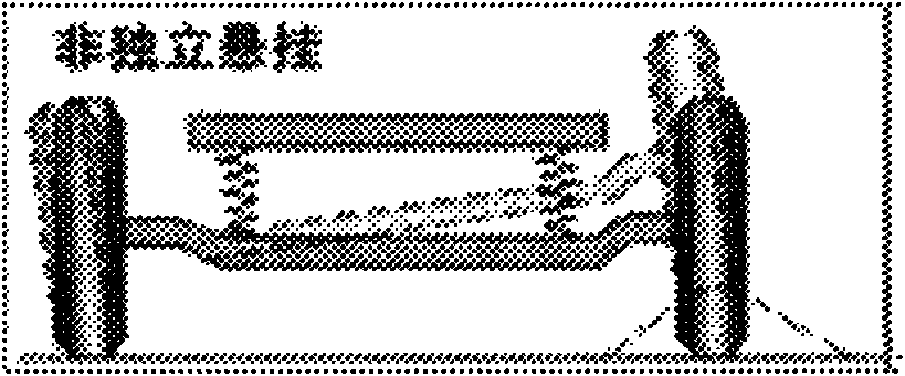
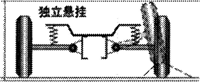
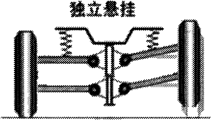
Technical field [0001] The invention relates to vehicle chassis technology, in particular to a self-compensating floating swing arm independent suspension system. Background technique [0002] By referring to "Automobile Technology", "Automobile Structure", "Detailed Explanation of the Advantages and Disadvantages of Various Suspension Forms" (excerpted from Liuzhou Automobile Network 2008-8-16) and other materials, and comparing with the existing technologies at home and abroad, the existing vehicle suspension system is generally Divided into two categories: non-independent suspension and independent suspension. It is also equipped with an anti-roll bar device to reduce the roll of the vehicle when turning. [0003] The structural feature of the non-independent suspension system is that the wheels on both sides are connected by an integral frame, and the wheels together with the axle are suspended under the frame or the body through an elastic suspension system. The non-i...

Claims


Application Information

Patent Timeline
Patent Type & Authority Patents(China)
IPC IPC(8): B60G21/05B60G7/02
CPCB60G7/02B60G7/001B60G2204/42B60G3/10B60G3/26B60G2200/46B60G2204/143
Inventor 侯贺
Owner 侯贺
Learn More