Wishbone shaped bell-less blast furnace distributor

A technology of distributor and bellless, applied in blast furnace, blast furnace details, blast furnace parts, etc., can solve the problems of difficult synchronization of three hydraulic cylinders, high cost of spare parts and maintenance, irreparable damage to the distributor, etc. To achieve the effect of controlling the tilting amount of the support ring, long service life and short transmission chain

Active Publication Date: 2012-02-29
李玉清 +1
View PDF3 Cites 16 Cited by
  • Summary
  • Abstract
  • Description
  • Claims
  • Application Information

AI Technical Summary

Problems solved by technology

[0010] The biggest problem of this mechanism is that the synchronization of the three hydraulic cylinders is not easy to achieve, the structure is complex, and there are many fault points. Once the three hydraulic cylinders are not synchronously linked, the damage to the distributor is often irreparable
[0012] The α-angle driving mechanism of the Luxembourg PW top distributor consist

Method used


Image

  • Wishbone shaped bell-less blast furnace distributor
  • Wishbone shaped bell-less blast furnace distributor
  • Wishbone shaped bell-less blast furnace distributor

Examples


Embodiment 1

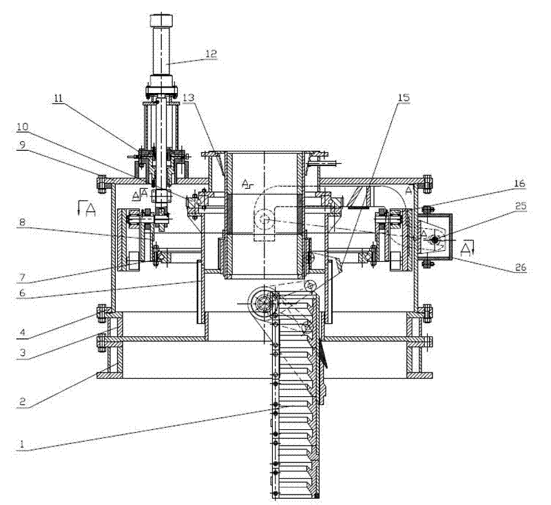
[0050] Embodiment 1: as Figures 1 to 8 A yoke-type bellless distributor for a blast furnace is shown, including a distributor box 4, a top cover 9, a water cooling plate 3, an upper slewing bearing 10, a rotating sleeve 6, a support ring 8, a lower slewing bearing 7, ear Shaft 19, trunnion crank 23, chute bracket 20, chute 1, throat 13 and horizontal transmission device 17 for controlling the β angle of the chute; Rotating sleeve, the center line of the rotating sleeve coincides with the center line of the blast furnace; the lower part of the support ring 8 is fixedly connected with the outer ring of the lower slewing bearing; the lower part of the rotating sleeve is symmetrically provided with trunnion sleeves. Two trunnions are worn, and the two trunnions are left and right symmetrical; the two sides of the chute bracket 20 are respectively fixedly connected with the two ends of the two trunnions located in the rotating sleeve, and the chute is hung on the chute bracket, an...

Embodiment 2

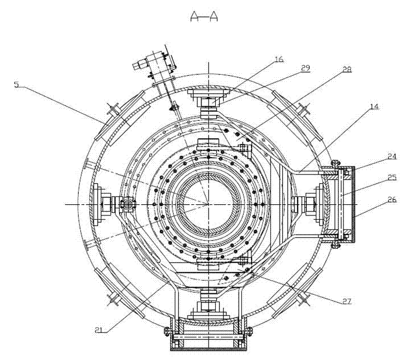
[0056] Embodiment 2: as Figure 9-16 As shown, the difference between this embodiment and Embodiment 1 lies in the supporting ring driving device. The supporting ring driving device in Embodiment 1 is provided with a set of hydraulic cylinders. In this embodiment, two sets of hydraulic cylinders are provided. The two sets of hydraulic cylinders Cylinders 12 are all vertically fixed on the top cover 9 of the distributor box, and the piston rod ends stretched into the distributor box are respectively hinged with the rigid drive arm 21; the rigid drive arm and the rigid balance arm The main function is to prevent the support ring from tilting during the up and down movement. In the actual application process, the two sets of rigid wishbone can be regarded as the anti-tilt mechanism. It can be applied to the existing distributor, and it can be combined with the existing single Arm double-link type or double-arm four-link type and other structural distributors are used together to ...


PUM


Abstract

The invention discloses a wishbone shaped bell-less blast furnace distributor. The distributor is characterized in that: the distributor comprises a distributor casing, a top cover, a water cooling disc, an upper slewing bearing, a rotation sleeve, trunnion rings, a lower slewing bearing, trunnions, trunnion cranks, a chute carriage, chutes, a venture, and a horizontal transmission device for controlling the beta angle of the chutes; the lower part of the trunnion ring is connected with the fixed ring of the lower slewing bearing; and two sides of the chute carriage are respectively hinged to the lower end of the rotation sleeve through two trunnions. A key improvement of the distributor is characterized in that: the distributor comprises a trunnion ring anti-tilting mechanism and a trunnion ring driving device for driving the trunnion ring to up-down move, and the trunnion ring anti-tilting mechanism comprises a rigid driving arm and a rigid balance arm. The distributor has the following advantages: a shortest driving chain is used to realize the radial component force-free and symmetrical two-point driving of the trunnion ring by a hydraulic cylinder, and the anti-tilting mechanism can effectively prevent the trunnion ring from tilting to all directions in the up-down movement process.

Description

technical field [0001] The invention relates to a blast furnace supporting equipment, in particular to a fork arm type blast furnace bellless distributor. Background technique [0002] The blast furnace chute distributor is the key equipment for blast furnace charging. Because of its flexible and uniform distribution characteristics, it has been widely used, and the flexible and stable movement of the chute is the key to the flexible and uniform distribution of the chute distributor. The position of the chute is controlled by its α angle and β angle relative to the axis of the distributor. The α angle is the angle between the chute and the axis of the distributor. One kind of movement is to change the angle between it and the axis of the distributor box, the purpose is to change the α angle of the chute, and the other is to drive the chute around the axis of the distributor by means of a driving device. The purpose is to change the β angle of the chute; the α angle of the c...

Claims


Application Information

Patent Timeline
IPC IPC(8): C21B7/00C21B7/20
Inventor 史振海李玉清
Owner 李玉清
Why Eureka
Try Eureka