
Resilient thimble for ball head of prosthetic joint

a prosthetic joint and ball head technology, applied in the field of prosthetic joints, can solve the problems of trunnion of the head spigot, poor patient care, and damage to the ball head, and achieve the effect of preventing structural damage and preventing damage to the head spigo

Inactive Publication Date: 2005-02-03
BENOIST GIRARD & CIE
View PDF0 Cites 36 Cited by
  • Summary
  • Abstract
  • Description
  • Claims
  • Application Information

AI Technical Summary

Benefits of technology

[0008] A thimble component made of a relatively resilient and deformable material such as titanium or titanium alloy can perform two functions. Firstly, it can absorb the defects of a damaged head spigot, so an imperfect femoral stem component would not need to be replaced during revision surgery.
[0009] Further, the resilient properties of the thimble can help to prevent structural damage being caused to the ceramics ball head by the less resilient head spigot during fitting and removal of the ball head and during loading of the joint. In addition, the thimble or sleeve can help to prevent damage being caused to the head trunnion if the ball head is not securely fitted thereon and makes minute movements during loading.

Problems solved by technology

However, ball heads of this type are relatively brittle and can be damaged when subjected to loading of the joint by the patient after surgery, for example during walking.
In these circumstances the spherical head needs to be replaced in revision surgery, which is bad for patients, particularly the elderly.
It can also occur as the result of the ball head failure.
Unfortunately, a new ceramics ball head cannot be fitted onto a damaged head spigot.
Scratches on the surface of a head spigot create ridges in the recess receiving the head which can fracture a ceramics ball head during fitting or joint loading, leading to prosthesis failure.
This significantly extends surgery time, which can be harmful to patients, particularly the elderly.

Method used


Image

  • Resilient thimble for ball head of prosthetic joint
  • Resilient thimble for ball head of prosthetic joint
  • Resilient thimble for ball head of prosthetic joint

Examples


Embodiment Construction

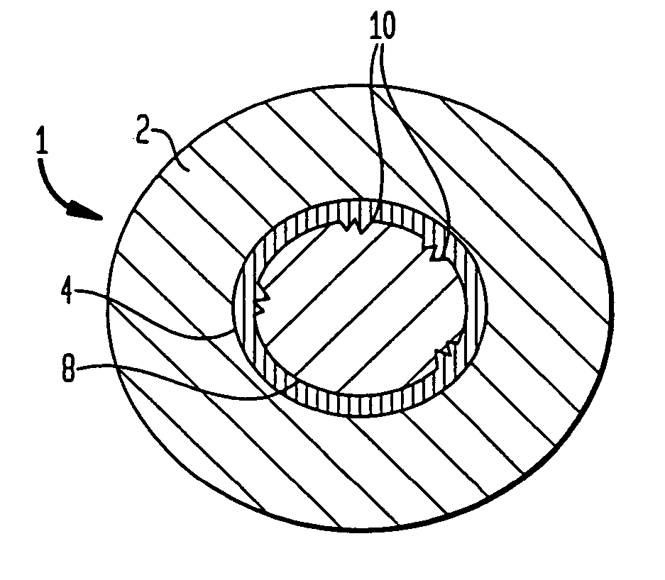
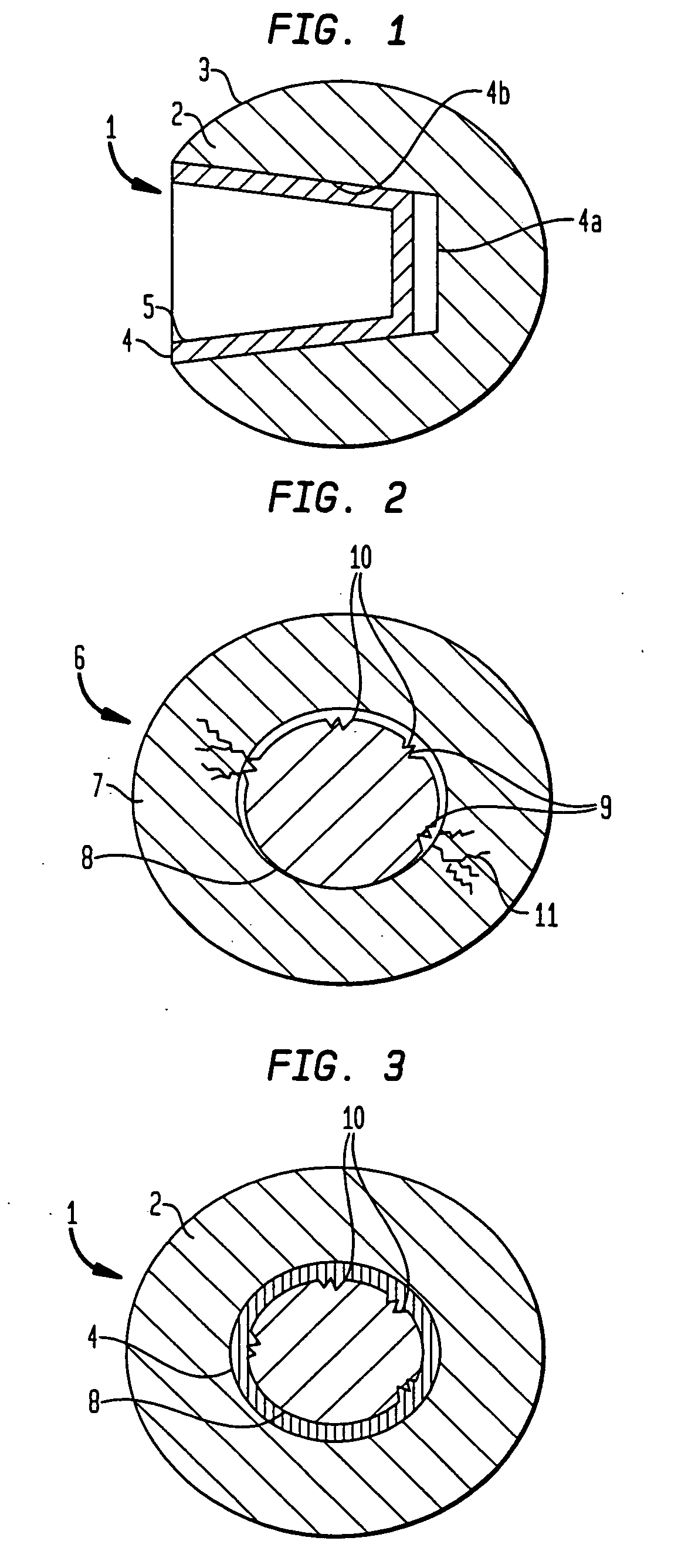
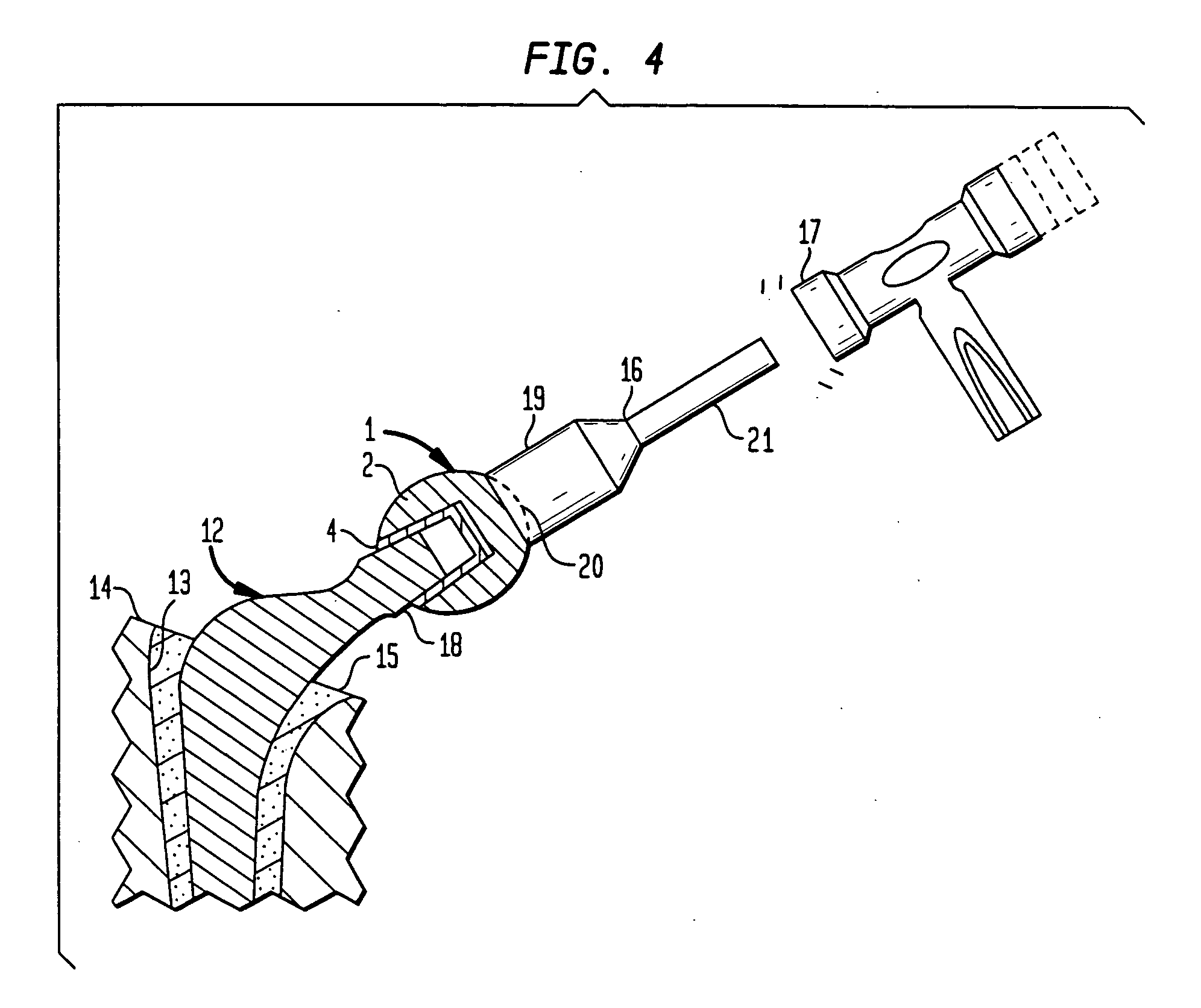
[0019] As shown in FIG. 1 a part-spherical or ball head 1 for a femoral prosthesis which head 1 has a body 2 formed from a ceramics material, for example, alumina. The body 2 has a smooth bearing surface 3. The body includes a recess 4b which, in the preferred embodiment, is conically tapered. The recess 4b could also be cylindrical. The ball head 1 is provided with a thimble or sleeve 4 constructed from a relatively resilient and deformable metal material when compared to the deformability of other metals such as stainless steel and cobalt-chrome molybdenum alloy (Vitallium®), for example titanium. In one embodiment, the sleeve 4 is secured inside the body 2 by means of a preloading procedure such as press fitting during construction. A void 4a is left between the sleeve 4 and the body 2. In the preferred embodiment, the inner surface 5 of the thimble 4 is formed as a Morse tapered socket or recess. The outer body contacting surface of the sleeve preferably is shaped to match the s...


PUM

PropertyMeasurementUnit
forceaaaaaaaaaa
forceaaaaaaaaaa
pressureaaaaaaaaaa

Abstract

A head component for use in a prosthetic joint such as a hip joint. The head has a body adapted to engage a natural acetabulum or a prosthetic acetabular cup component. The head has a recess with a resilient sleeve located therein adapted to engage the trunnion of a prosthetic stem component with which it is to be used. The sleeve material is more deformable than the trunnion material and can deform under sufficient force to absorb any unevenness in the trunnion surface.

Description

CROSS-REFERENCE TO RELATED APPLICATION [0001] This application is a divisional of U.S. application Ser. No. 10 / 243,425 filed Sep. 13, 2002.BACKGROUND OF THE INVENTION [0002] This invention relates to the ball head of a prosthetic joint particularly, but not exclusively, for use in a replacement hip joint, a prosthesis incorporating such a ball head, and a method of assembly thereof. [0003] For example, the Exeter and Charnley type femoral prostheses are well known and comprise a stem for implantation into the medullary canal and have a neck at the proximal end which carries a ball or spherical head portion or a spigot or trunnion for cooperation with a ball head component. With the Exeter design the ball head is dimensioned to cooperate with an acetabular cup prosthesis implanted into the acetabulum. With the Charnley design the ball head is sometimes dimensioned to cooperate with the natural acetabulum. [0004] It is common for the femoral prostheses to be provided with a modular he...

Claims


Application Information

Patent Timeline
Patent Type & Authority Applications(United States)
IPC IPC(8): A61L27/00A61F2/00A61F2/30A61F2/32A61F2/34A61F2/36A61F2/46
CPCA61F2/30723A61F2310/00203A61F2/36A61F2/3609A61F2/3676A61F2/4637A61F2002/3021A61F2002/30217A61F2002/30332A61F2002/30474A61F2002/30485A61F2002/30563A61F2002/30612A61F2002/3069A61F2002/3493A61F2002/3611A61F2002/3625A61F2002/365A61F2002/4623A61F2002/4631A61F2002/4681A61F2220/0025A61F2220/0033A61F2230/0067A61F2310/00023A61F2/32A61F2/4603A61F2002/30604
Inventor CUEILLE, CHRISTOPHERAUGEL, PATRICK
Owner BENOIST GIRARD & CIE
Learn More