Prefabricated transverse H-shaped underground continuous wall joint section structure

A technology for underground diaphragm walls and joints, which is applied to underwater structures, infrastructure engineering, artificial islands, etc., can solve problems such as width exceeding the design width, quality accidents, and difficulty in verticality control, so as to ensure width and quality, save construction period and cost, and lengthen the effect of seepage bypass path

Inactive Publication Date: 2012-02-29
天津一建建筑工程有限公司
View PDF5 Cites 11 Cited by
  • Summary
  • Abstract
  • Description
  • Claims
  • Application Information

AI Technical Summary

Problems solved by technology

[0004] 1. The groove wall is not vertical, causing the position of the locking tube to shift
[0005] Due to construction machinery and manual reasons, there is always a problem that the two ends of the finished tank wall are not vertical at the lower part
This results in that when the lock pipe is lowered, the lock pipe cannot be placed in the pre-placed position, which affects the width of the wall and the lowering of the reinforcement cage.
At the same time, the gap behind the lock pipe is too large, which increases the workload of earthwork backfill and is prone to the problem of grout leakage
[0006] 2. The locking tube is not fixed stably, causing the locking tube to tilt
[0007] The fixation of the lock pipe includes upper end fixation and lower end fixation: the upper end fixation can be seen and touched, and is easy to control; the lower end fixation is mainly lifted by a crane to a certain height of the lock mouth pipe so that it can freely fall and insert into the soil to fix it. The method is properly controlled, and the lower end of the lock pipe generally does not have a large displacement, but it is difficult to control the quality of underwater operations
It is very easy to cause the locking tube to be unstable and cause the locking tube to tilt
[0008] 3. The problem of backfilling after the lock pipe
[0009] After the lock pipe is lowered, it will not be close to the soil, and there will always be a certain gap, and the earthwork must be backfilled, otherwise the concrete will bypass the lock pipe, which will cause great obstacles to the construction of the next continuous wall
However, due to the small gap and full of mud, backfilling is not easy to compact
[0010] 4. The horizontal stiffness of the lock pipe is small, and the lateral pressure is large when the concrete is poured, and its verticality is difficult to control
[0011] In actual construction, if there is a horizontal deviation of the locking pipe, it will inevitably cause the width of this wall to exceed the design width, occupying the width of the next wall
The occurrence of this problem and the occurrence of grout leakage jointly caused the problem of narrowing the width of the closed width, causing the vertical joints of each ground connection wall to be not straight and tight, and leakage is very easy to occur
[0012] 5. The problem of pulling out the lock pipe
[0013] It is the key to grasp the initial setting time of concrete when pulling out the lock pipe. In actual operation, due to poor grasp of the initial setting time, pulling out early will cause quality accidents. It is difficult to pull out or even break the mouth tube, which is time-consuming and labor-intensive, and may cause quality accidents, which is difficult to handle

Method used


Image

  • Prefabricated transverse H-shaped underground continuous wall joint section structure
  • Prefabricated transverse H-shaped underground continuous wall joint section structure
  • Prefabricated transverse H-shaped underground continuous wall joint section structure

Examples


Embodiment Construction

[0024] The joint section structure of the prefabricated I-shaped underground diaphragm wall of the present invention is described in conjunction with the accompanying drawings.

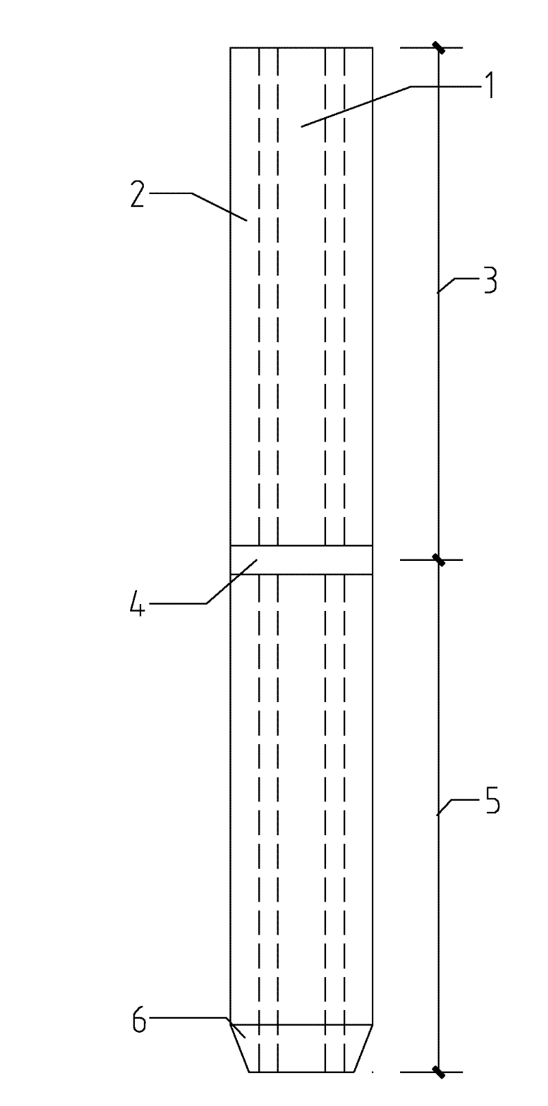
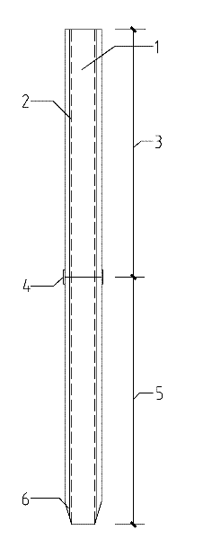
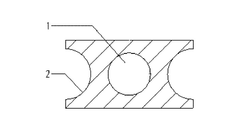
[0025] The structure of the joint section of the prefabricated I-shaped underground diaphragm wall of the present invention is: the two side ends of the cross section of the joint section are semicircular grooves 1, the middle part of the cross section of the joint section is a circular hole 2, and the joint section The section is divided into multiple length sections longitudinally, and a connecting steel plate is provided on the outside of the junction of every two length sections, and blade feet 6 are provided around the bottom of the joint section, and the length of the joint section is not less than 1500mm.

[0026] Such as Figure 1-a , Figure 1-b , figure 2 , image 3 As shown, the joint section structure of the prefabricated I-shaped underground diaphragm wall of the present invention, the...


PUM

PropertyMeasurementUnit
Lengthaaaaaaaaaa

Abstract

The invention provides a prefabricated transverse H-shaped underground continuous wall joint section structure. Two side end parts of the cross section of a joint section are provided with semicircular grooves, the middle part of the cross section of the joint section is provided with a circular hole, the joint section is longitudinally divided into a plurality of length sections, a connecting steel plate is arranged at the outer side of the joint of every two length sections, and four sides of the bottom of the joint section are provided with edge feet. The structure has the advantages that: the prefabricated transverse H-shaped underground continuous wall joint section replaces ground connected wall joint equipment and replaces a part of cast-in-place ground connected wall structure, so that the process of pulling the joint equipment is avoided and the construction period and the manufacturing cost are saved; the lower end of the joint section is wedge-shaped and inserted into soil by means of gravity, so that the lower end is effectively fixed, and the width and the quality of the cast-in-place breadth can be effectively ensured; the designed width of the prefabricated continuous wall joint breadth is not less than 1,500 millimeters, and the bypass seepage path of concrete is lengthened; by curved surface design of the contact face of the prefabricated continuous wall joint breadth and the cast-in-place ground connected wall, the seepage problem of the ground connected wall is effectively solved; and the prefabricated continuous wall joint section is made into a member cancelled structure by adopting proper length section by section, so the structure is convenient to transport and hoist.

Description

technical field [0001] The invention relates to a building basic structure component, in particular to a prefabricated I-shaped underground continuous wall joint section structure. Background technique [0002] In 1950, Italy began to use underground diaphragm wall technology in reservoir dam engineering, and in 1958, my country introduced this technology. In the mid-1970s, this technology began to be applied to construction, coal mining, municipal and other industries. As an enclosure structure of underground engineering, ground connection wall is widely used in deep foundation pit engineering. It can be used as a temporary retaining and water-stop structure, or it can replace the basement exterior wall as a permanent underground structure. [0003] The construction of the ground connection wall is mainly divided into: guide wall construction, reinforcement cage production, mud production, trough setting out, trough formation, lower lock pipe, steel cage hoisting and lowe...

Claims


Application Information

Patent Timeline
IPC IPC(8): E02D5/20E02D19/18E02D29/02E02D17/04
Inventor 赵锡铭王强尹洪江李建军毕江寰肖海波赵旭光刘江松毛繁刘迎鑫张振辉
Owner 天津一建建筑工程有限公司
Why Eureka
Try Eureka