
Low temperature optical system support device with high heat insulation efficiency and small thermal stress influence

A heat insulation efficiency and optical system technology, applied in the field of low-temperature optics of aerospace optical remote sensors, can solve problems such as deformation of low-temperature optical systems, affecting imaging quality, and difficult realization of support, and achieve the requirements of improving heat insulation efficiency, ensuring accuracy, and ensuring accuracy Effect

Active Publication Date: 2013-08-28
北京航天创智科技有限公司
View PDF4 Cites 0 Cited by
  • Summary
  • Abstract
  • Description
  • Claims
  • Application Information

AI Technical Summary

Problems solved by technology

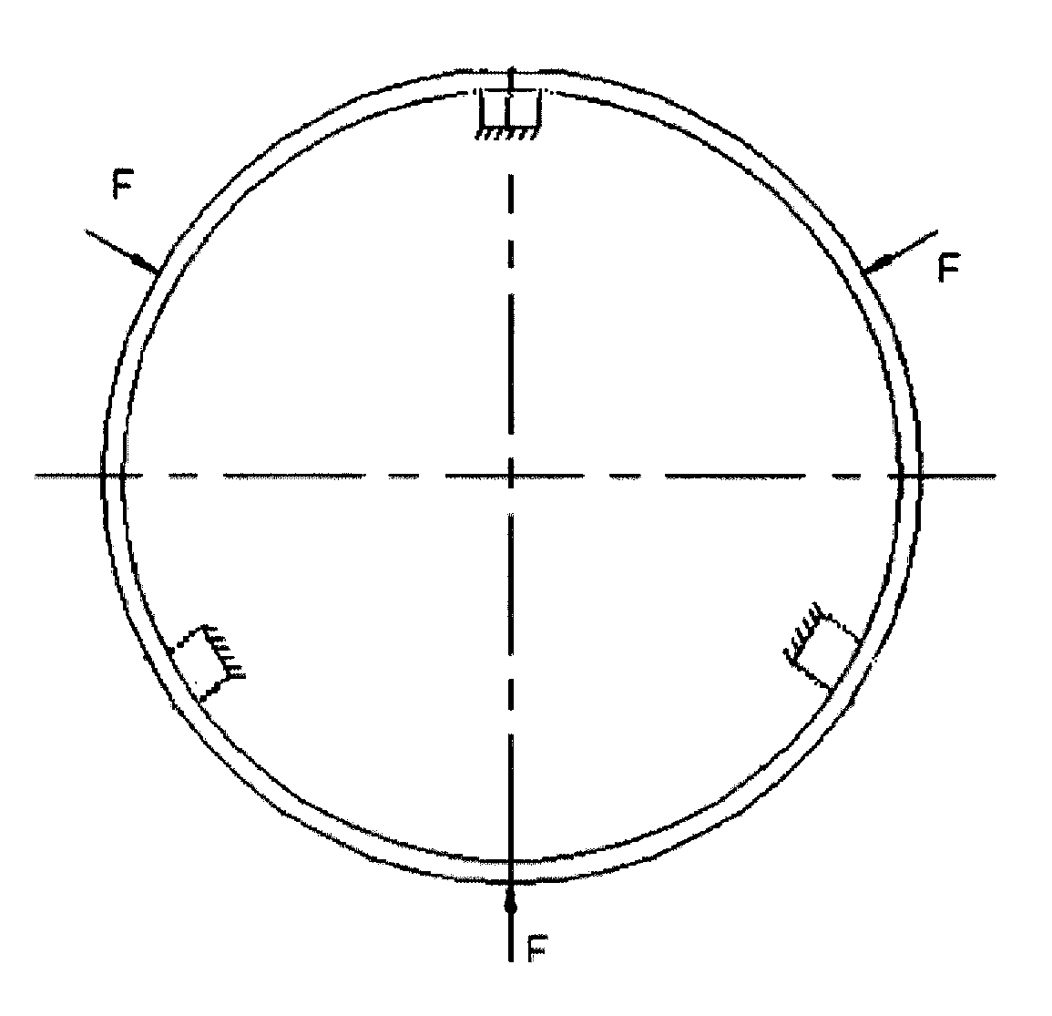
It is difficult to meet the requirements of heat insulation efficiency and support stiffness in the form of plastic heat insulation sleeves, and it is difficult to realize the support of low-temperature optical systems with large temperature differences; although glass fiber reinforced plastic rod supports can properly improve heat insulation efficiency and ensure a certain support stiffness, but Because thermal deformation will generate a lot of force on the optical system, it will cause deformation of the low temperature optical system and seriously affect the imaging quality

Method used


Image

  • Low temperature optical system support device with high heat insulation efficiency and small thermal stress influence
  • Low temperature optical system support device with high heat insulation efficiency and small thermal stress influence
  • Low temperature optical system support device with high heat insulation efficiency and small thermal stress influence

Examples


Embodiment Construction

[0019] Below in conjunction with accompanying drawing and specific embodiment the present invention is described in further detail:

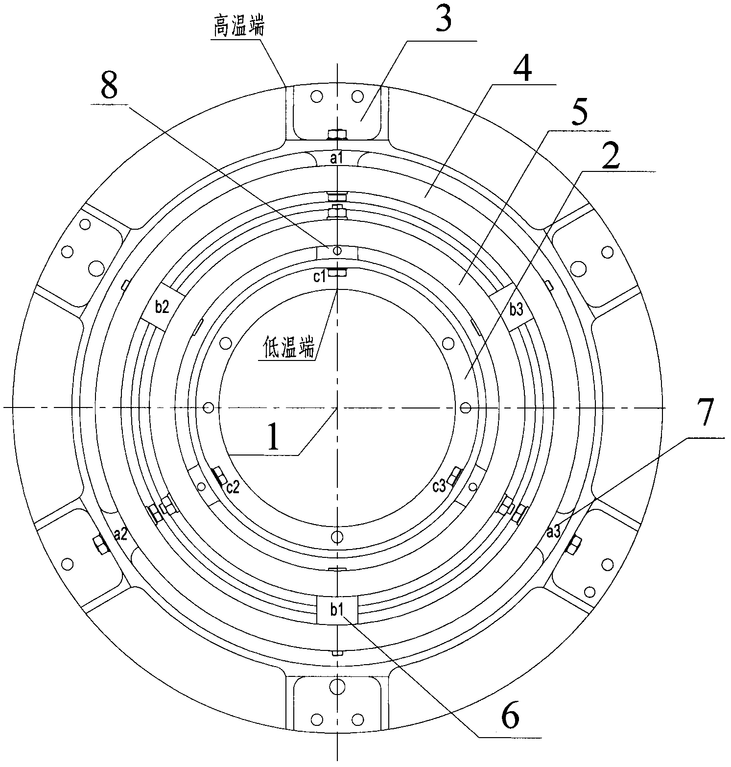
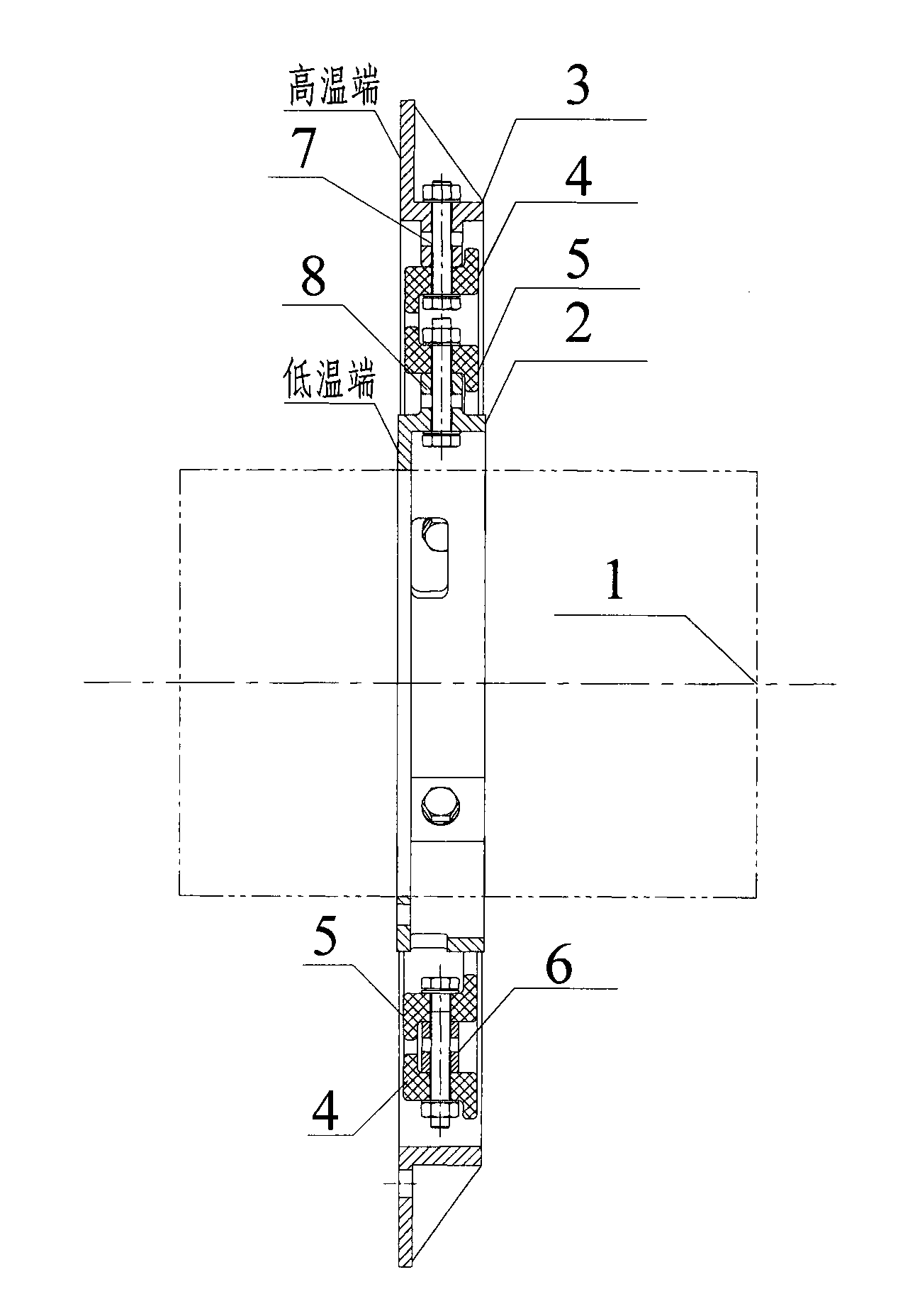
[0020] Such as figure 1 Shown is a schematic diagram of the structure of the low-temperature optical system supporting device of the present invention, figure 2 Shown is a cross-sectional view of the structure of the low-temperature optical system support device of the present invention. It can be seen from the figure that the support device includes a support inner ring 2, a support outer ring 3, a first heat insulation ring 4, a second heat insulation ring 5, and three transition blocks 6 , three first support blocks 7 and three second support blocks 8, wherein the optical system 1 is placed inside the support inner ring 2 and connected to the support inner ring 2, and the support inner ring 2 and the second heat insulation ring 5 pass through the uniform distribution Three second support blocks 8 ( figure 1 c1, c2, c3) in the fixed connect...


PUM


Abstract

The invention relates to a low temperature optical system support device with high heat insulation efficiency and small thermal stress influence. In the device, a support inner ring is fixedly connected with a second heat insulation ring through three second support blocks which are uniformly distributed at the periphery of the support inner ring; the second heat insulation ring is fixedly connected with a first heat insulation ring through three transition blocks which are uniformly distributed at the periphery of the second heat insulation ring; and the first heat insulation ring is fixedlyconnected with a support outer ring through three first support blocks which are uniformly distributed at the periphery of the support outer ring. By the support device with a dual glass reinforced plastic annular structural form, a heat conduction path is prolonged, the thermal resistance between a high temperature end and a low temperature end is increased, and the heat insulation efficiency ofthe component is greatly improved; and as a flexible link in the structural component, the glass reinforced plastic annular structure bears main thermal deformation, reduces applied force acting on an optical system, ensures the precision of the optical system and improves the detecting capability of the optical system.

Description

technical field [0001] The invention belongs to the field of low-temperature optics of aerospace optical remote sensors, and relates to a low-temperature optical system supporting device with high heat insulation efficiency and low thermal stress influence. Background technique [0002] With the rapid development of aerospace optical remote sensor technology, the requirements for the infrared detection capability of the deep space low temperature background of the optical remote sensor are also getting higher and higher. Target detection, in order to reduce the heat leakage of the low-temperature optical system, reduce the requirements of the remote sensor on the space cooling system capacity, and reduce the thermal deformation and thermal stress of the optical system, to ensure the accuracy of the optical system, high heat insulation efficiency, small thermal The design of support structures affected by stress is of great significance. At present, the structural forms that...

Claims


Application Information

Patent Timeline
Patent Type & Authority Patents(China)
IPC IPC(8): G02B7/00G01J5/02
Inventor 刘义良周峰行麦玲王莹吴利民王彬
Owner 北京航天创智科技有限公司
Learn More