Air suction focusing sprinkling device

一种喷洒装置、吸气通道的技术,应用在吸气聚焦型喷洒装置领域,能够解决水花效果未有提升等问题,达到配件少、结构牢固、吸气效果明显的效果

Active Publication Date: 2012-03-07
XIAMEN SOLEX HIGH TECH IND CO LTD
View PDF9 Cites 3 Cited by
  • Summary
  • Abstract
  • Description
  • Claims
  • Application Information

AI Technical Summary

Problems solved by technology

[0003] How to spread the sprayed liquid, the traditional way is shower head and other devices, this kind of device structure is simple and easy to implement, but it also has its weakness, that is, it only sprays out the water path of the liquid, and the effect of the spray is not improved

Method used


Image

  • Air suction focusing sprinkling device
  • Air suction focusing sprinkling device
  • Air suction focusing sprinkling device

Examples


Embodiment 1

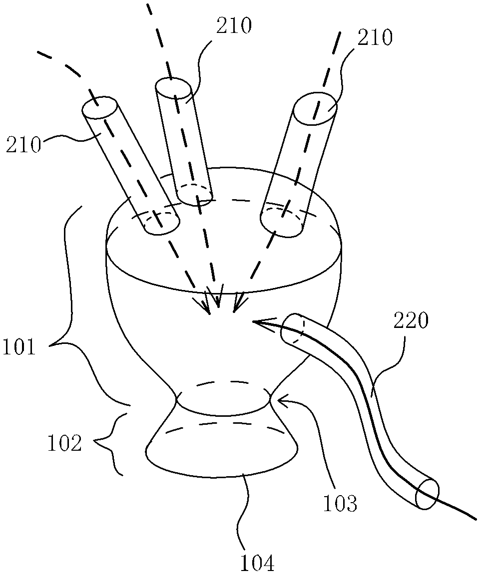
[0029] Such as figure 1 As shown, a three-dimensional schematic diagram of Embodiment 1 of the present invention; the converging cavity 101 is integrally connected with the rectifying port 102 and has a smooth inner surface; the large end of the converging cavity 101 is on the top and the small end is on the bottom, and the two gradually transition; The place is the throat 103, and the throat 103 gradually expands to the spout 104.

[0030] There are three water inlet passages 210, the entrances of which are before the large end of the converging chamber 101, and the extension lines of the three water inlet passages 210 in the converging chamber, or the paths of their respective water flows, have an intersection in the converging chamber 101, Such setting is very important, the purpose is to make the water flows from the water inlet channel 210 collide with each other.

[0031] There is a suction passage 220 on the side wall of the converging chamber 101, and the outside of t...

Embodiment 2

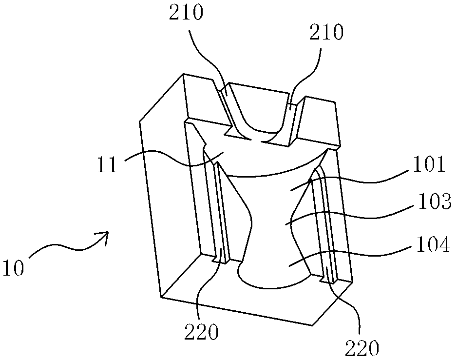
[0033] Such as figure 2 It is a schematic diagram of the upper mosaic block in Embodiment 2 of the present invention; image 3 It is a schematic diagram of the lower mosaic block in Embodiment 2 of the present invention; Figure 4 It is a schematic diagram of the second embodiment of the present invention. The details of Embodiment 2 are described in conjunction with these three figures:

[0034] The upper mosaic block 10 and the lower mosaic block 20 have a joint surface with a rectangular outline. After the two mosaic blocks are closely matched, a hexahedral fitting is obtained; in the upper mosaic block 10, there are two water inlet channels 210, which are formed in the form of grooves On the upper mosaic block 10; there is an upper cavity 11 formed on the upper mosaic block, which is divided into three sections, which belong to the respective halves of the converging cavity 101, the throat 103 and the rectifying port 104; there are two symmetrical The suction channel 2...


PUM


Abstract

The invention discloses an air suction focusing sprinkling device, which is characterized by comprising a converging cavity, at least two water inlet channels, at least one air suction channel and a rectifying port, wherein the converging cavity is provided with a large end and a small end of unequal sizes in the axial direction; an inner wall between the large end and the small end is in gradualtransition; the water inlet channels are communicated to the large end of the converging cavity; all water inlet channels are joined in the converging cavity towards a water outflow direction in the converging cavity; the air suction channel is communicated with the converging cavity from an external free space; the rectifying port is communicated with the small end of the converging cavity, and is provided with a throat for making water current form a liquid seal; the cross section of the throat is 1-3 times the maximum total cross sectional area of the water inlet channels; and the rectifying port gradually becomes larger from the throat to an outer cross section. The converging cavity of which the large and small ends are in gradual transition is matched with the throat which can form the liquid seal and the air suction channel for mixing air, so that the focusing and air sucking effects of water current in the converging cavity are remarkable, collision between the air and the water current is enhanced, a good outputted water particle sprinkling effect is achieved, and a large range is realized.

Description

technical field [0001] The invention relates to a component for distributing liquid output, in particular to a spraying device of the suction focusing type. Background technique [0002] In many fields, such as showering, cleaning, etc., it is usually necessary to spray the liquid; this type of spraying is to discharge the liquid from the pipeline, and has a certain spray effect, such as the spraying range needs to be wide enough. [0003] How to spread the sprayed liquid, the traditional way is shower head and other devices, this type of device structure is simple and easy to implement, but it also has its weakness, that is, it only sprays out the liquid by shaping the waterway, and the effect of the spray is not There is an improvement. [0004] Therefore, there is a demand, that is, how to design a simple device, so that the liquid flow can generate a larger spray output, and at the same time, the spray particle effect and water saving effect of the spray are better. C...

Claims


Application Information

Patent Timeline
Patent Type & Authority Applications(China)
IPC IPC(8): B05B1/34
CPCA61M11/06A61M11/002B05B7/0425B05B7/0483
Inventor 冀洋锋曹勇斌陈斌周华松
Owner XIAMEN SOLEX HIGH TECH IND CO LTD
Why Eureka
Try Eureka