
Direct current supply geothermal heating device

A geothermal heating and DC power supply technology, applied in the field of electric heating, can solve the problems of hidden danger, leakage current, large leakage current, etc., and achieve the effects of improving safety, reasonable design and simple structure

Active Publication Date: 2012-03-07
中惠地热股份有限公司
View PDF10 Cites 0 Cited by
  • Summary
  • Abstract
  • Description
  • Claims
  • Application Information

AI Technical Summary

Problems solved by technology

[0003] At present, all electric heating systems use AC power supply. Due to the capacitive effect of the electrothermal film, leakage current will be generated, and the leakage current is relatively large, which is often greater than the operating current of the leakage protection device (the requirements for electrical equipment in my country must be within the load line of the equipment. There is a leakage protection device at the front end), which has certain potential safety hazards
In addition, since the heating system uses AC power supply, electromagnetic radiation problems will inevitably occur, and long-term use will also have a certain impact on human health

Method used


Image

  • Direct current supply geothermal heating device
  • Direct current supply geothermal heating device
  • Direct current supply geothermal heating device

Examples


specific Embodiment approach 1

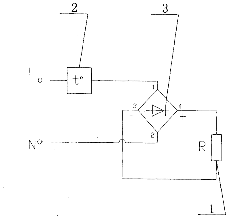
[0021] Specific implementation mode one: refer to figure 1 , the specific embodiment adopts the following technical scheme: it includes a heating element 1, a thermostat 2 and a rectifier 3, the live wire L is connected to one end of the thermostat 2, and the other end of the thermostat 2 is connected to 1 end of the rectifier 3, Terminal 4 of the rectifier 3 is connected to one end of the heating element 1, the other end of the heating element 1 is connected to terminal 3 of the rectifier 3, and terminal 2 of the rectifier 3 is connected to the neutral line N.

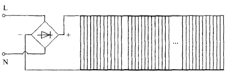
[0022] The setting positions of the rectifier 3 include centralized setting and decentralized setting.

[0023] Whether the rectifier 3 is centrally installed or distributed, its rectification methods include full-wave rectification and half-wave rectification, and the full-wave rectification is composed of 4 diodes, and the half-wave rectification is composed of 2 diodes.

[0024] When the rectifiers 3 are arranged ...

specific Embodiment approach 2

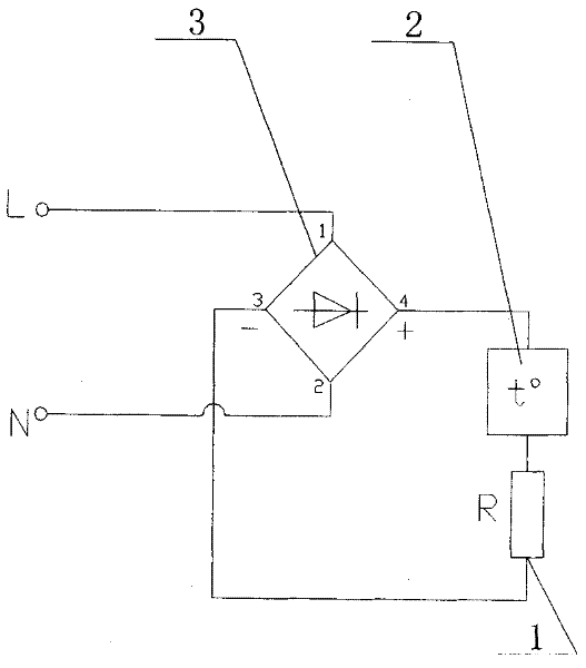
[0027] Specific implementation mode two: refer to figure 2 The difference between this specific embodiment and specific embodiment 1 is that the live wire L is connected to one end of the rectifier 3, the fourth end of the rectifier 3 is connected to one end of the thermostat 2, and the other end of the thermostat 2 is connected to the heating element 1. One end is connected, the other end of the heating element 1 is connected to the 3rd end of the rectifier 3, and the 2nd end of the rectifier 3 is connected to the neutral line N. Its composition and connection relationship are the same as those in the first embodiment.


PUM


Abstract

The invention relates to a direct current supply geothermal heating device, and relates to the technical field of electric heating. The heating device comprises a heating unit (1), a temperature controller (2) and a rectifier (3), wherein a live wire L is connected with one end of the temperature controller (2); the other end of the temperature controller (2) is connected with the 1st end of the rectifier (3); the 4th end of the rectifier (3) is connected with one end of the heating unit (1); the other end of the heating unit (1) is connected with the 3rd end of the rectifier (3); and the 2nd end of the rectifier (3) is connected with a zero line N. The heating device provided by the invention has the advantages of reasonable design, and simple structure; direct current supply technology is adopted, the problems of leakage current of an electric heating system and electromagnetic radiation are simultaneously solved, the security of the electric heating system is improved, and the electric heating system is a development tendency of the electric heating system in future.

Description

Technical field: [0001] The invention relates to the technical field of electric heating, in particular to a geothermal heating device powered by direct current. Background technique: [0002] Electric geothermal heating has become one of the important heating methods in my country. It has many advantages such as convenient construction, simple control, convenient adjustment, energy saving, and maintenance-free, and is more and more valued and favored by people. Through patent retrieval, it is found that the patent requirements for electric heating technology are mostly concentrated on the research on the material, shape, and structure of heating elements (cables, electric heating films, etc.). For example: Patent Application No. 200610027098.5 discloses a nano-intelligent temperature control cable and its preparation method and a geothermal heating system using it; Patent Application No. 200910066661.3 discloses a geothermal cable; Geothermal heating system with rod-shaped...

Claims


Application Information

Patent Timeline
Patent Type & Authority Applications(China)
IPC IPC(8): F24D13/02F24D19/10
CPCY02B10/40
Inventor 丁宝张永明尹会涞乔世军卢晓敏
Owner 中惠地热股份有限公司
Learn More