Control system and method for energy recovery of flow battery device

A flow battery and energy recovery technology, applied in battery circuit devices, circuit devices, fuel cells, etc., can solve the problems of inability to achieve black start of flow battery devices, increasing equipment volume and investment cost, and lack of energy recovery.

Active Publication Date: 2018-06-01
SHANGHAI ELECTRICGROUP CORP
View PDF10 Cites 4 Cited by
  • Summary
  • Abstract
  • Description
  • Claims
  • Application Information

AI Technical Summary

Problems solved by technology

[0017] The technical problem to be solved by the present invention is to overcome the failure of energy recovery in the existing liquid flow battery device; when the liquid flow battery device is stopped, the continuous operation of the liquid flow battery device cannot be realized; when the liquid flow battery device When it is in the shutdown state, it is impossible to realize the black start function of the flow battery device; and the power module in the existing flow battery device contains multiple modules, which increases the defects of equipment volume and investment cost, and the purpose is to provide a Control method and system for energy recovery of flow battery device

Method used


Image

  • Control system and method for energy recovery of flow battery device
  • Control system and method for energy recovery of flow battery device
  • Control system and method for energy recovery of flow battery device

Examples


Embodiment 1

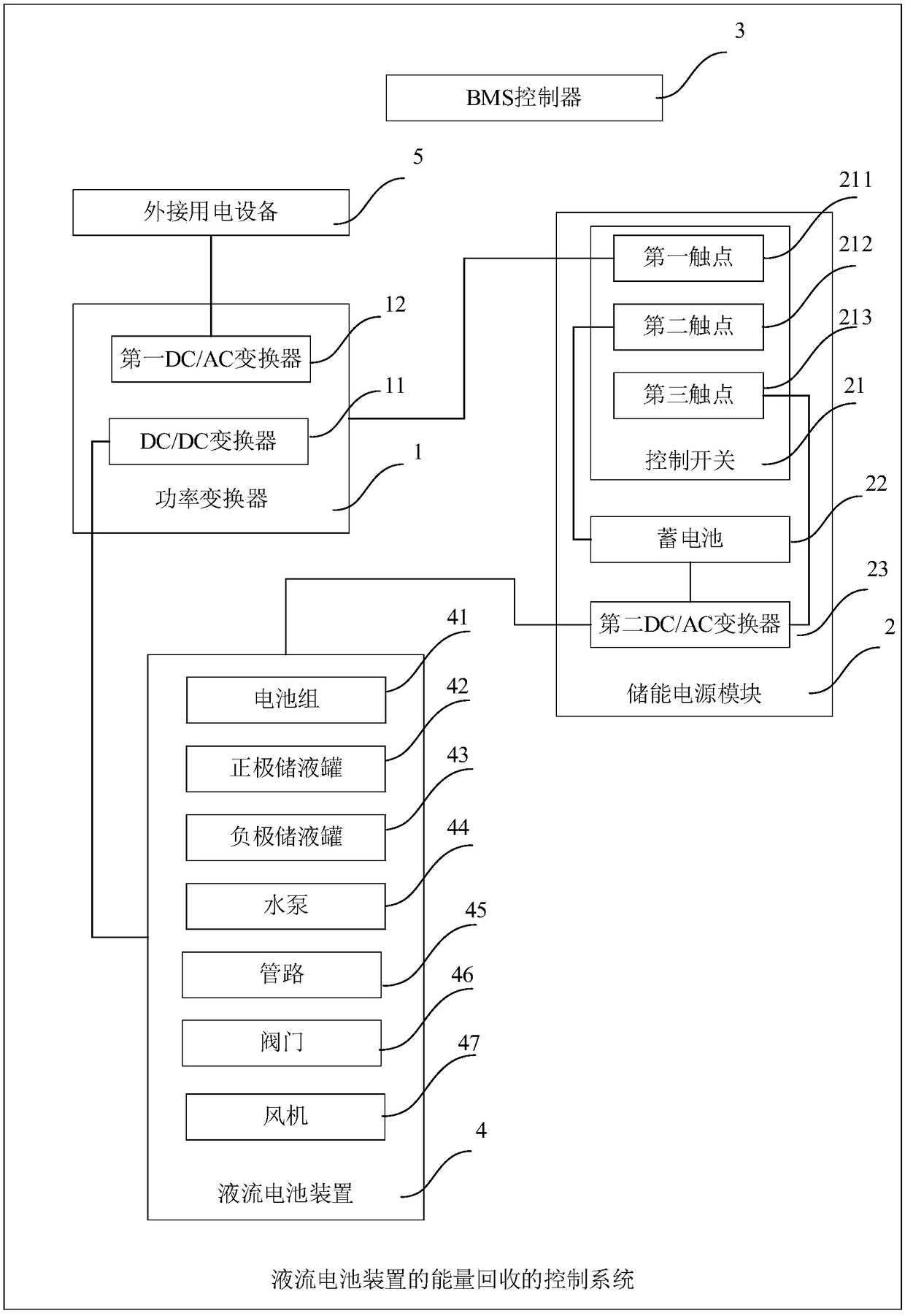
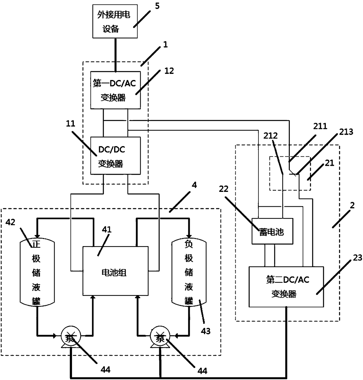
[0087] Such as figure 1 and figure 2 As shown, the energy recovery control system of the flow battery device in this embodiment includes a power converter 1 , an energy storage power supply module 2 and a BMS controller 3 .

[0088] The BMS controller 3 is connected in communication with the power converter 1 and the energy storage power supply module 2 respectively.

[0089] The power converter 1 includes a DC / DC converter 11 and a first DC / AC converter 12 , and the DC / DC converter 11 is electrically connected to an external device through the first DC / AC converter 12 .

[0090] The DC / DC converter 11 is electrically connected to the flow battery device 4 and is used for boosting the DC voltage output by the flow battery device 4 .

[0091]When the flow battery device is in discharge mode, the DC / DC converter is used to boost the DC voltage output by the flow battery device; the first DC / AC converter 12 is used to convert the The DC voltage output by the DC / DC converter 1...

Embodiment 2

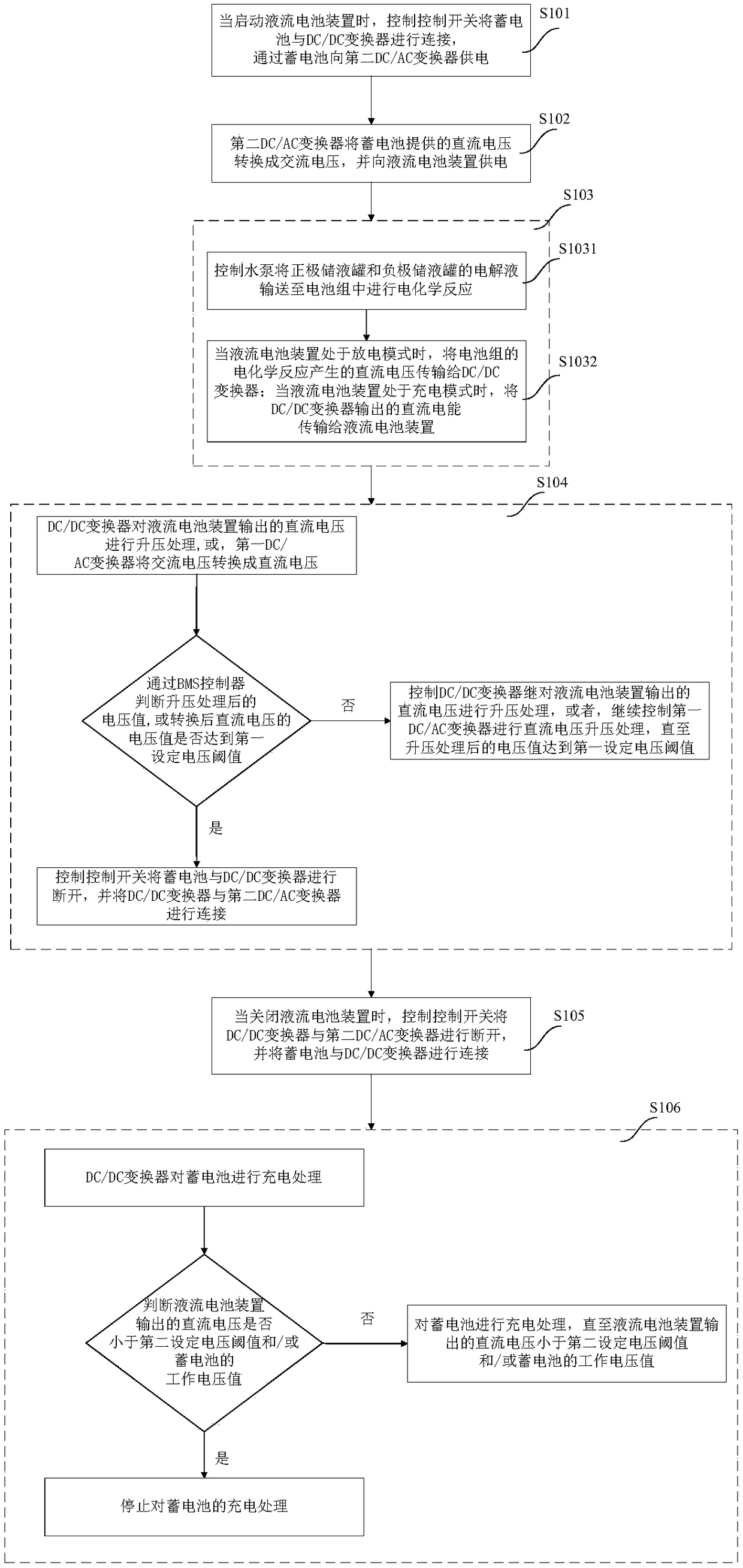
[0112] Such as image 3 As shown, the energy recovery control method of the flow battery device in this embodiment includes:

[0113] S101. When starting the flow battery device, control the control switch to connect the battery to the DC / DC converter, and supply power to the second DC / AC converter through the battery;

[0114] S102. The second DC / AC converter converts the DC voltage provided by the storage battery into an AC voltage, and supplies power to the flow battery device;

[0115] S103. Obtain the working mode of the flow battery device. When the flow battery device is in the discharge mode, the flow battery device undergoes an electrochemical reaction and outputs a DC voltage to the DC / DC converter;

[0116] When the flow battery device is in the charging mode, the flow battery device undergoes an electrochemical reaction and receives DC power provided by the DC / DC converter;

[0117] Wherein, the liquid flow battery device includes a battery pack, a positive elect...


PUM


Abstract

The invention discloses a control system and method for energy recovery of a flow battery device. The control system comprises a power converter, an energy storage power supply module and a BMS controller. The power converter is used for boosting a DC voltage outputted by a flow battery device and supplying power to an external device. The BMS controller is used for switching the working mode of the energy storage power supply module. The energy storage power supply module is used for self-charging, and also supplies power to the flow battery device. The control system and method of the invention complete the recovery of the remaining energy in a battery pack, and solve the leakage current problem existing in the existing flow battery device; and can achieve the continuous operation of theflow battery device through a storage battery when the flow battery device is stopped and achieve the black start of the flow battery device through the storage battery when the flow battery device is in a shutdown state, and overcome the defects of a plurality of modules included in the power supply module in the existing flow battery device, thereby reducing the equipment size and reducing theinvestment cost.

Description

technical field [0001] The present invention relates to the technical field of liquid flow battery energy storage management, in particular to a control method and system for energy recovery of a liquid flow battery device. Background technique [0002] Because flow batteries have the advantages of flexible design, good charge and discharge performance, free site selection, safety and environmental protection, and low maintenance costs, they can be used in renewable energy power generation systems such as wind energy and solar energy. Now liquid flow batteries have become the main choice for power grid load shifting and balancing power supply and demand, and have broad application prospects in the field of large-capacity energy storage. [0003] The flow battery device is composed of battery pack, electrolyte, liquid storage tank and pipeline. When the flow battery device is working, the electrolyte is transported from the liquid storage tank to the battery pack through the...

Claims


Application Information

Patent Timeline
Patent Type & Authority Applications(China)
IPC IPC(8): H02J7/00H02J7/06H01M8/18H01M8/04186
CPCH02J7/0077H02J2007/10H01M8/04201H01M8/188H02J7/0068H02J7/06Y02E60/50
Inventor 李峰李杨王云李福生
Owner SHANGHAI ELECTRICGROUP CORP
Why Eureka
Try Eureka