Non-isolated intermediate-point clamping photovoltaic grid connected inverter and modulation method thereof
A non-isolation and inverter technology, applied in the direction of photovoltaic power generation, AC network circuit, single-network parallel feeding arrangement, etc., can solve the problems of increasing cost, volume and loss, affecting reliability, and not being able to completely cut off the leakage current loop , to achieve the ability to suppress leakage current and solve the effect of leakage current
- Summary
- Abstract
- Description
- Claims
- Application Information
AI Technical Summary
Problems solved by technology
Method used
Image
Examples
Embodiment 1
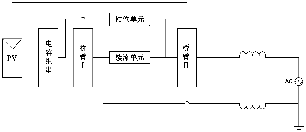
[0039] as attached figure 1 As shown, a non-isolated mid-point clamped photovoltaic grid-connected inverter is set between the photovoltaic array output unit and the AC grid, which includes a capacitor string 1, a clamp unit 3, a freewheeling unit 5, and a bridge arm I2 and bridge arm II4; the bridge arm I2 is respectively connected in parallel with the capacitor string 1, the bridge arm II4 and the photovoltaic array output unit; the positive end of the clamping unit 3 is respectively connected to the freewheeling unit 5 connected to the bridge arm II4, the negative terminal of the clamping unit 3 is connected to the midpoint of the capacitor string 1; one end of the freewheeling unit 5 is connected to the positive terminal of the clamping unit 3, and the other One end is connected to the midpoint of the bridge arm I2; point a of the bridge arm I2 and point b of the bridge arm II4 form the AC voltage output terminal u of the non-isolated midpoint clamp photovoltaic grid-conne...
Embodiment 2
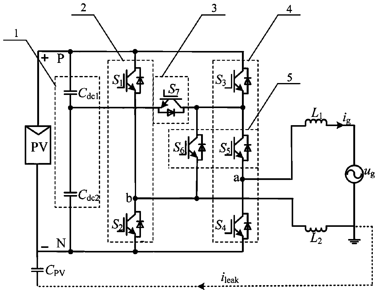
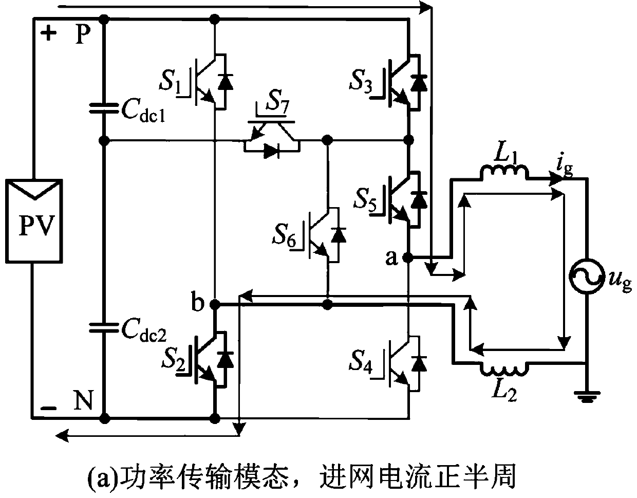
[0042] This embodiment provides a specific implementation of the non-isolated neutral point clamped photovoltaic grid-connected inverter, as shown in the attached figure 2 As shown, the capacitor string 1 is composed of equivalent DC input voltage dividing capacitors C connected in series dc1 and C dc2 Composed, the freewheeling unit 5 includes a switching tube S 5 and switch tube S 6 , the clamping unit 3 is a switching tube S 7 , the bridge arm I2 includes forward-series switching tubes S 1 and switch tube S 2 , the bridge arm II 4 includes forward-series switching tubes S 3 , switch tube S 5 and switch tube S 4 , each of the switching tubes is connected in reverse parallel with a freewheeling diode; wherein, the switching tube S of the clamping unit 7 The positive end of the bridge arm II and the switching tube S 3 connected to the negative terminal of the clamp unit, the switching tube S 7 The negative end of the capacitor string is connected to the midpoint; th...
Embodiment 3
[0065] In this embodiment, the non-isolated neutral point clamped photovoltaic grid-connected inverter and its modulation method are verified by simulation.
[0066] Setting: DC input voltage is 400V, AC grid voltage is 380V / 50Hz, output filter inductance L 1 and filter inductor L 2 is 4mH, the DC bus capacitance is 2200μF, the distributed capacitance is 120nF, the switching frequency is 15kHz, and the switching junction capacitance is 1.5nF.
[0067] as attached Figure 13 As shown, this embodiment gives the bridge arm output voltage u of the non-isolated neutral point clamped photovoltaic grid-connected inverter ab The simulation waveform of the bridge arm midpoint (a, b) to the DC bus negative terminal N point voltage u aN and u bN The simulation waveform of the simulation waveform, and the simulation waveform of the common-mode voltage, the common-mode voltage remains constant throughout the switching cycle, u cm Both are 200V.
[0068] as attached Figure 14 As sho...
PUM
 Abstract
Description
Claims
Application Information
 - R&D
- Intellectual Property
- Life Sciences
- Materials
- Tech Scout
- Unparalleled Data Quality
- Higher Quality Content
- 60% Fewer Hallucinations
Browse by: Latest US Patents, China's latest patents, Technical Efficacy Thesaurus, Application Domain, Technology Topic, Popular Technical Reports.
© 2025 PatSnap. All rights reserved.Legal|Privacy policy|Modern Slavery Act Transparency Statement|Sitemap|About US| Contact US: help@patsnap.com


