Power factor compensation control circuit of self-turn-off device

A power factor compensation and control circuit technology, applied in reactive power compensation, reactive power adjustment/elimination/compensation, etc., can solve problems such as inability to adapt to dynamic control compensation current, restricting the promotion and application of compensation equipment, and complex structure of compensation equipment , to achieve the effect of reducing the number of control circuits, simple structure and low cost

Inactive Publication Date: 2012-03-07
BEIJING QU CHUANG ELECTRIC TECH
View PDF3 Cites 4 Cited by
  • Summary
  • Abstract
  • Description
  • Claims
  • Application Information

AI Technical Summary

Problems solved by technology

Power capacitors generally use current-limiting resistors or inductors to limit excessive instantaneous current when switching, which has the disadvantages of large volume, high loss and high cost.
Although the new thyristor controlled zero-point switching can overcome the above shortcomings, due to the inherent non-self-shutoff characteristics of the thyristor device, it can only solve the current limiting problem of switching, but cannot adapt to the dynamic control compensation current that changes with the load. Requirements, inevitably lead to undercompensation and overcompensation; on the other hand, the combination of multiple sets of capacitors makes the compensation equipment complex in structure, high in cost, difficult to use and maintain, and the compensation equipment is only suitable for high-power users, not suitable for power consumption It accounts for the majority of users from kilowatts to tens of kilowatts, which seriously restricts the promotion and application of compensation equipment

Method used


Image

  • Power factor compensation control circuit of self-turn-off device
  • Power factor compensation control circuit of self-turn-off device
  • Power factor compensation control circuit of self-turn-off device

Examples


Embodiment Construction

[0028] The present invention will be described in further detail below in conjunction with the embodiments and accompanying drawings.

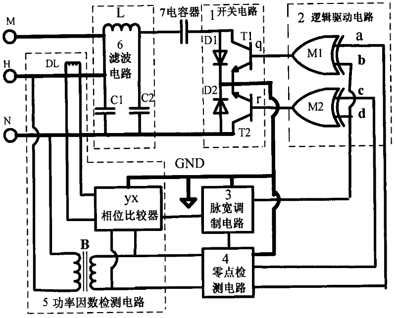
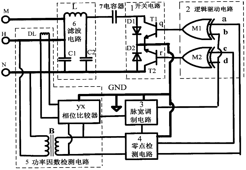
[0029] The invention is a self-shutdown device power factor compensation control circuit. figure 1 It is a schematic circuit diagram of a self-shutdown device capacitor power factor compensation control device implemented by the circuit. The circuit consists of a switch circuit 1, a logic drive circuit 2, a pulse width modulation circuit 3, a zero point detection circuit 4, a power factor detection circuit 5, a filter circuit 6, a capacitor 7, an AC input terminal H, an output terminal M and a common terminal N. . When the input terminal H and the common ground terminal N are connected to the AC power, the output terminal M and the common ground terminal N are connected to the load, the current is filtered by the capacitor C1, the inductance L, and the capacitor C2 in the filter circuit 6, and then the capacitor 7 passes through the switch ci...


PUM


Abstract

The invention discloses a power factor compensation control circuit of a self-turn-off device. The power factor compensation control circuit mainly comprises a switch circuit, a logic drive circuit, a pulse width modulation circuit, a zero point detection circuit, a power factor detection circuit, a filter circuit and a capacitor. By using the characteristic of turn-off control of the self-turn-off device, two self-turn-off devices connected in parallel with diodes are adopted to form the switch circuit, and the switch circuit is controlled to carry out charge and discharge voltage control on the capacitor, thus the control over the power factor compensation is realized. According to the power factor compensation control device manufactured in the invention, the number of the control circuit is reduced by using one group of capacitor to replace multiple groups of traditional combined capacitors, the loss is little because a zero point soft switch controls charge and discharge, not only can automatic control be realized, but also the advantages of simple structure, low cost, convenience for use and maintenance, and the like are achieved, and the power factor compensation control circuit is especially suitable for wide range of users consuming power of thousands Watt to tens of thousands of Watt.

Description

technical field [0001] The invention belongs to the technical field of electric power engineering, and relates to power factor compensation control of electric equipment. Background technique [0002] Using capacitors for power factor compensation is a popular and recognized power-saving method at present. Most of the existing compensation circuits are combined and controlled by computers to multiple groups of power capacitors to realize quantitative compensation of power factors. Power capacitors generally use current-limiting resistors or inductors to limit excessive instantaneous current when switching, which has the disadvantages of large volume, high loss and high cost. Although the new thyristor controlled zero-point switching can overcome the above shortcomings, due to the inherent non-self-shutoff characteristics of the thyristor device, it can only solve the current limiting problem of switching, but cannot adapt to the dynamic control compensation current that chan...

Claims


Application Information

Patent Timeline
Patent Type & Authority Applications(China)
IPC IPC(8): H02J3/18
CPCY02E40/30
Inventor 李香龙张炜毛书凡
Owner BEIJING QU CHUANG ELECTRIC TECH
Why Eureka
Try Eureka