
Flow device comprising a cavity cooling system

A technology of flow device and cavitation, which is applied to parts of pumping devices for elastic fluids, air transportation, engine components, etc., can solve problems such as temperature life and strength temperature limitations, achieve geometric shape optimization, improve life, easy-to-achieve effects

Inactive Publication Date: 2012-03-07
MTU AERO ENGINES GMBH
View PDF10 Cites 0 Cited by
  • Summary
  • Abstract
  • Description
  • Claims
  • Application Information

AI Technical Summary

Problems solved by technology

But this causes an additional heating of the edge layers, thus intensifying the influence of the hotter edge layers
As a result of this influence, the sealing elements, the sealing bodies and the grooves on the rotor side for fastening the rotor blades are subjected to particularly high temperatures and are temperature-limited in terms of their life and strength.

Method used


Image

  • Flow device comprising a cavity cooling system
  • Flow device comprising a cavity cooling system
  • Flow device comprising a cavity cooling system

Examples


Embodiment Construction

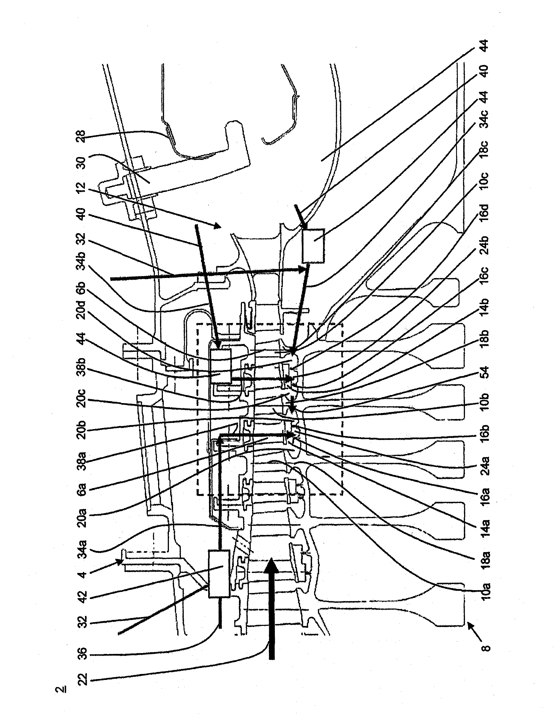
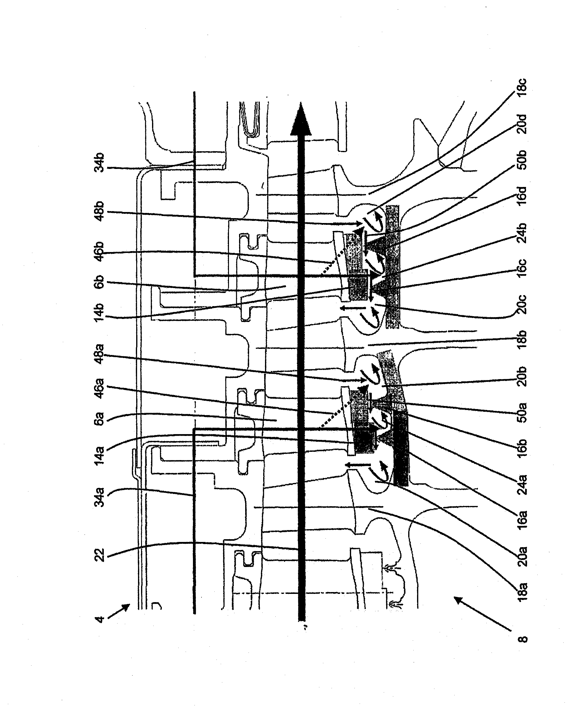
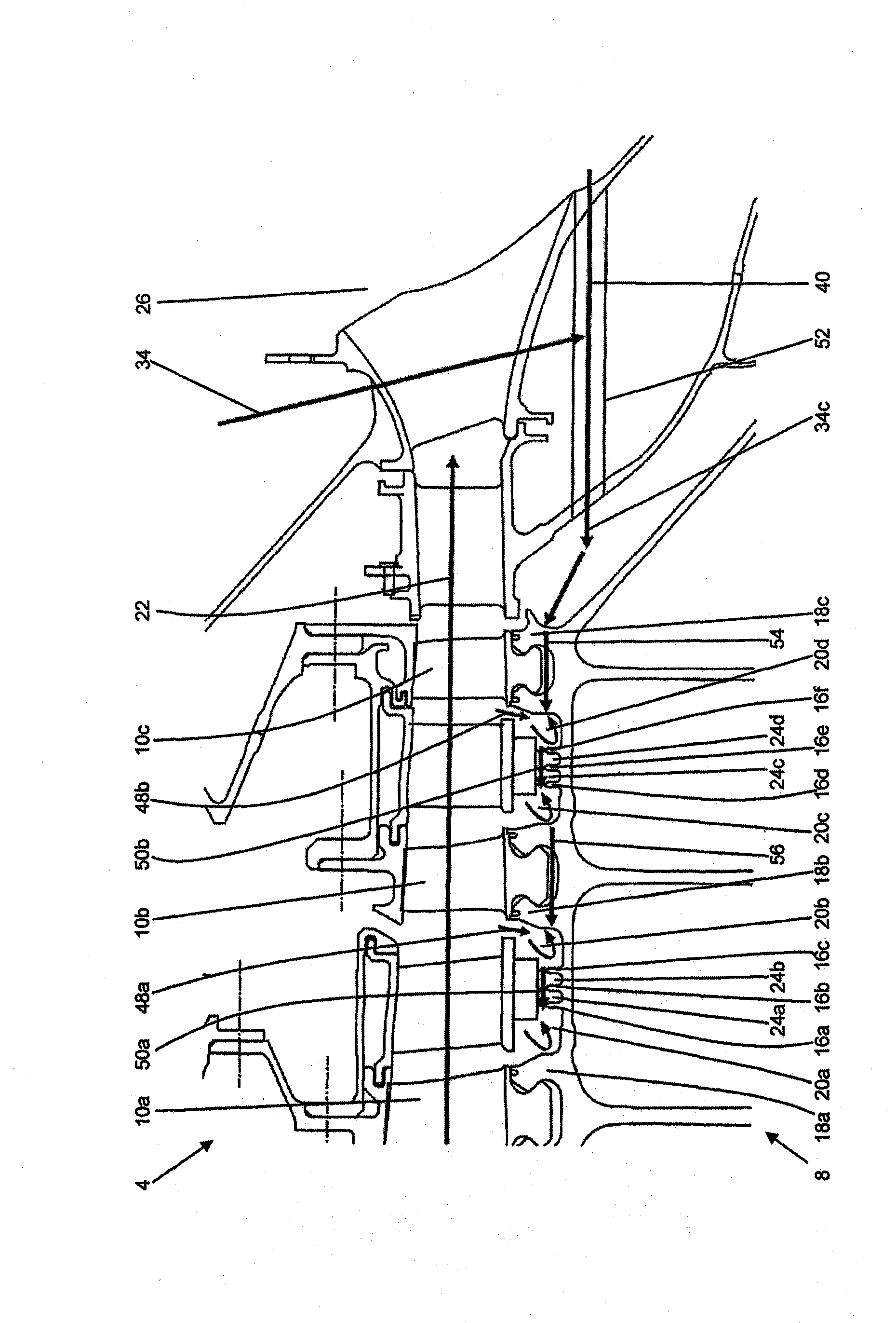
[0017] figure 1 A longitudinal section through the high-pressure region of a flow device designed as a compressor 2 with a cooling air injection system according to the invention is shown. here, in figure 1 Various types of cooling air injection systems are shown in , which can be operated individually or in combination with each other.

[0018] The compressor 2 has an axial design and is part of a gas turbine, in particular an aircraft engine. It has a multi-part housing 4 which supports a plurality of guide vanes 6a, 6b and in which a rotor 8 with a plurality of rotor blades 10a, 10b, . . . is rotatably mounted. Guide vanes 6 a , 6 b and rotor blades 10 a , 10 b , .

[0019] The guide vanes 6a, 6b each bear at their tips a wrapping strip which is provided on its side facing the rotor 8 with a honeycomb-shaped and plate-shaped sealing element 14a, 14b.

[0020] On the rotor side facing the sealing elements 14a, 14b radial flange-shaped or land-shaped sealing bodies 16a, 1...


PUM


Abstract

The invention relates to a flow device comprising a cooling air injection system for injecting cooling air into cavities (20, 24) between sealing elements (14a, 14b) or sealing bodies (16a, 16b,...) on the side of the guide vanes and the rotor.

Description

technical field [0001] The invention relates to a flow arrangement for a gas turbine according to the preamble of claim 1 . Background technique [0002] Such a flow device designed as a compressor is shown, for example, in the applicant's German patent application DE 10 2005 045 255 A1. Such compressors for gas turbines are designed axially and have a multi-part housing in which a rotor with a large number of rotor blades is rotatably mounted. Between the rotor blades extend guide vanes fixed on the housing side. Plate-shaped sealing elements are arranged on the guide vanes, which interact with opposing radial collar-shaped sealing bodies of the rotor. The individual sealing elements and the individual sealing bodies form a plurality of axially adjoining cavities, so-called inner-air-sealing cavities. During compressor operation, the air flowing from a main flow into the cavities is heated more strongly in subsequent compressor stages than the air in the main flow or in ...

Claims


Application Information

Patent Timeline
Patent Type & Authority Applications(China)
IPC IPC(8): F04D29/58F01D11/04
CPCF01D11/04F04D29/102F04D29/542F04D29/584F05D2260/205Y02T50/60
Inventor K·P·吕德D·科赫W·胡姆豪泽
Owner MTU AERO ENGINES GMBH
Learn More