
Bearing seat of working roller of cold rolling machine

A technology for work rolls and chocks, which is applied in the direction of metal rolling mill stands, metal rolling stands, and metal rolling, and can solve the problem of easy scratches on work roll chocks and small liners, which affect the rolling accuracy of rolling mills and product quality. Quality is difficult to control and other problems, to achieve the effect of simple structure, improved production efficiency and high work efficiency

Inactive Publication Date: 2012-03-14
WUXI WUYE HEAVY IND MACHINERY
View PDF6 Cites 0 Cited by
  • Summary
  • Abstract
  • Description
  • Claims
  • Application Information

AI Technical Summary

Problems solved by technology

[0002] At present, in the widely used four-high cold rolling mill, there is no chamfering at the front end of the work roll, or the chamfering is random, so that during the roll change process of the work roll, when the work roll is loaded into the frame, it is easy to be connected with the machine The collision of the liner plate of the small window of the frame made the work roll bearing seat and the small liner plate easy to be scratched, and it was quite difficult to install, which seriously affected the rolling accuracy of the rolling mill, resulting in unstable quality of the products rolled out of the rolling mill. Product quality is difficult to control, reducing the benefits of enterprises

Method used


Image

  • Bearing seat of working roller of cold rolling machine
  • Bearing seat of working roller of cold rolling machine

Examples


Embodiment Construction

[0009] The present invention will be further described below in conjunction with specific drawings and embodiments.

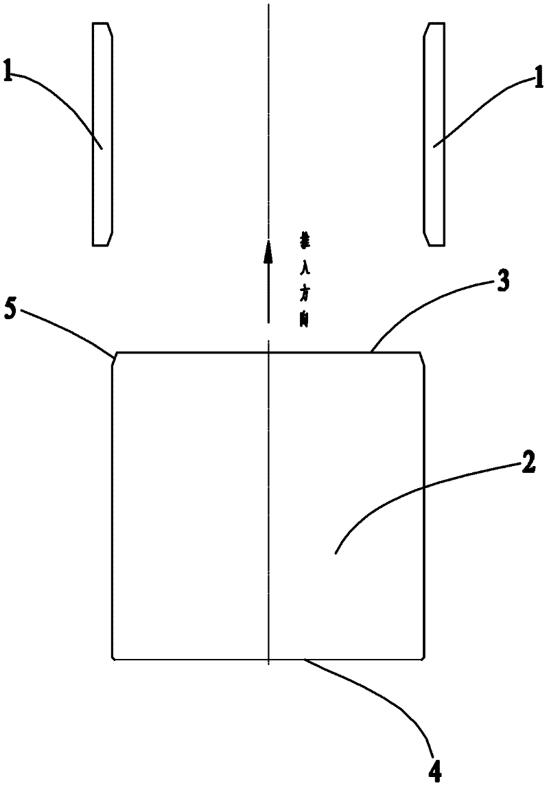
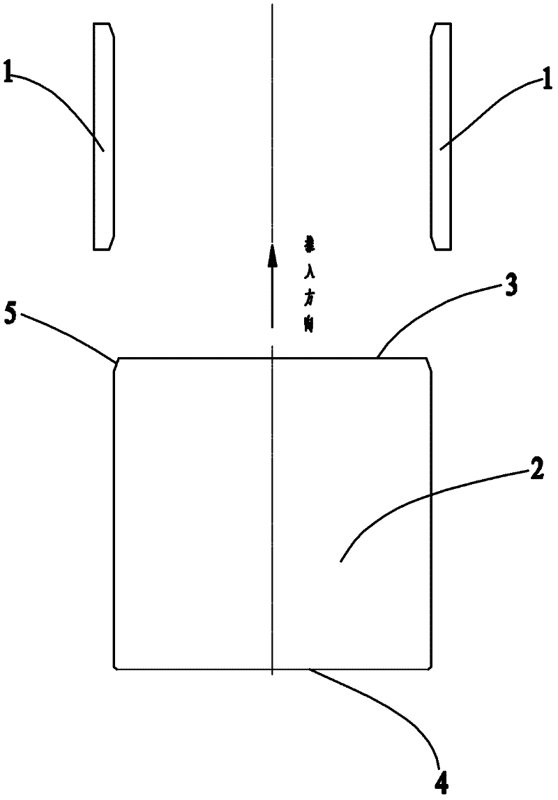
[0010] Such as figure 1 Shown: the frame small liner 1, the work roll bearing housing body 2, the first end 3, the second end 4 and the chamfer 5.

[0011] Such as figure 1 Shown: the cold rolling mill work roll chock includes a work roll chock body 2, the work roll chock body 2 includes a first end 3 and a second end 4, at the first end of the work roll chock body 2 3 is provided with symmetrically distributed chamfers 5, and the size of the chamfers 5 is 10×15°.

[0012] In a four-high cold rolling mill, symmetrically distributed chamfers 5 are provided on the first end 3 of the work roll chock body 2, so that when the work roll is loaded into the stand through the work roll chock body 2, the first end 3 chamfer 5, as a guide, it is easy to install the work roll system into the frame, avoiding the difficulty of the work roll system entering the frame when changin...


PUM


Abstract

The invention relates to a bearing seat of a working roller of a cold rolling machine, which comprises a bearing seat body of a working roller; and the first end of the bearing seat body of the working roller is provided with chamfers which are symmetrically distributed. According to the bearing seat of the working roller of the cold rolling machine, the chamfers which are symmetrically distributed are arranged on the first end of the bearing seat body of the working roller in a four-roller cold rolling machine. In this way, a working roller system can be arranged into a rack very easily by utilizing the chamfers at the first end as a guide when the working roller is arranged into the rack by the bearing seat body of the working roller, and the defects that the working roller system is difficult to enter the rack when a roller is exchanged and the bearing seat body of the working roller is easy to scratch with a small lining plate of the rack are avoided. Meanwhile, the labor intensity of a worker is lowered, and the production efficiency is enhanced; moreover, the chamfers at the corresponding first end of the bearing seat body of the working roller are simple to manufacture, the installation of the roller system is convenient and easy, the labor intensity is small, the auxiliary time is little, the working efficiency is high, and the quality stability of a rolled product is enhanced; and moreover, the structure is simple, and the manufacture is convenient.

Description

Technical field [0001] The invention relates to a bearing seat, in particular to a cold rolling mill work roll bearing seat, belonging to the technical field of cold rolling mills. Background technique [0002] At present, in the widely used four-high cold rolling mill, the front end of the work roll is not chamfered, or it is chamfered at will. In this way, when the work roll is installed in the stand during the work roll change, it is easy to contact the machine. The collision of the lining plate of the small window of the frame makes the work roll chock and the small lining plate easy to scratch, and it is quite difficult to install, which seriously affects the rolling accuracy of the rolling mill and causes the quality of the products rolled by the rolling mill to be unstable. Product quality is difficult to control, which reduces the efficiency of the enterprise. Summary of the invention [0003] The purpose of the present invention is to overcome the deficiencies in the pri...

Claims


Application Information

Patent Timeline
Patent Type & Authority Applications(China)
IPC IPC(8): B21B31/02
Inventor 周小芳
Owner WUXI WUYE HEAVY IND MACHINERY
Learn More