Clamping device for manipulator

A technology of manipulators and grippers, which is applied in the field of manipulator gripping devices, can solve the problems of unfavorable production capacity improvement, energy saving and emission reduction, inconvenient installation, commissioning and transportation, and bulky volume, etc., to improve production capacity and production efficiency, with simple structure and small size Effect

Inactive Publication Date: 2012-03-14
SHENZHEN FUTAIHONG PRECISION IND CO LTD
View PDF5 Cites 44 Cited by
  • Summary
  • Abstract
  • Description
  • Claims
  • Application Information

AI Technical Summary

Problems solved by technology

[0002] Existing manipulators used on molding machines are generally bulky and heavy, and are extremely inconvenient for installation, commissioning, and transportation, and consume high energy; it is not conducive to the improvement of production capacity and the development trend of energy conservation and emission reduction.

Method used


Image

  • Clamping device for manipulator
  • Clamping device for manipulator
  • Clamping device for manipulator

Examples


Embodiment Construction

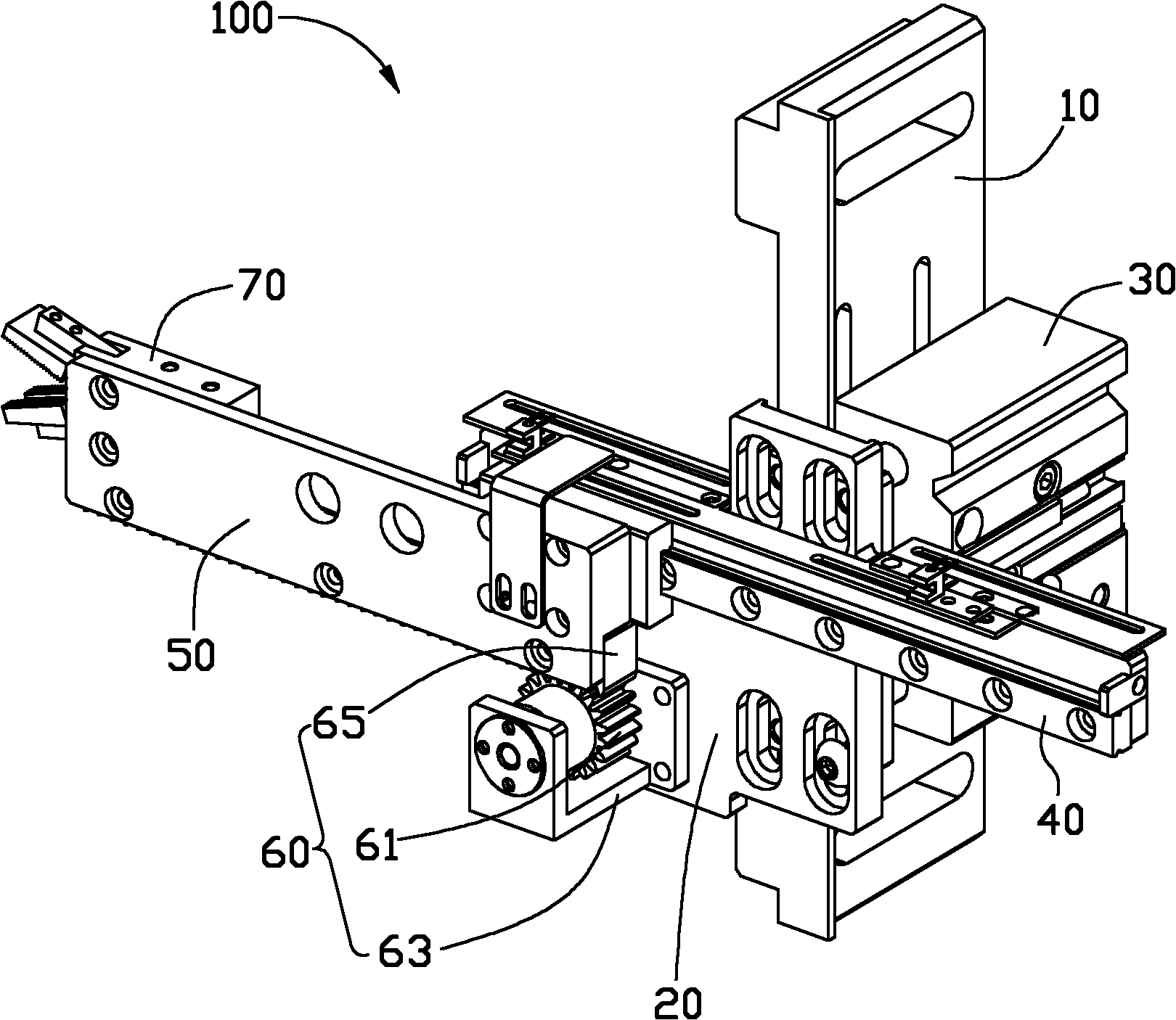
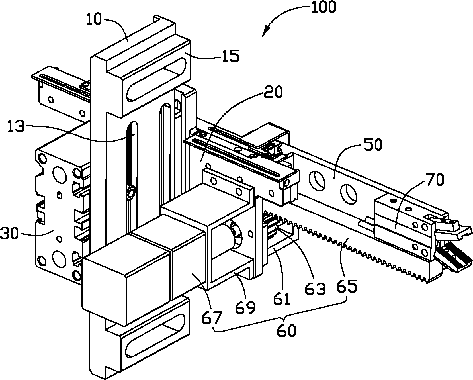
[0013] see figure 1 and figure 2 , the manipulator clamping device of the present invention is a preferred embodiment of the manipulator clamping device 100 applied in a molding equipment (not shown). The manipulator gripping device 100 can extend into the forming equipment to grip the formed workpiece and take out the gripped workpiece.

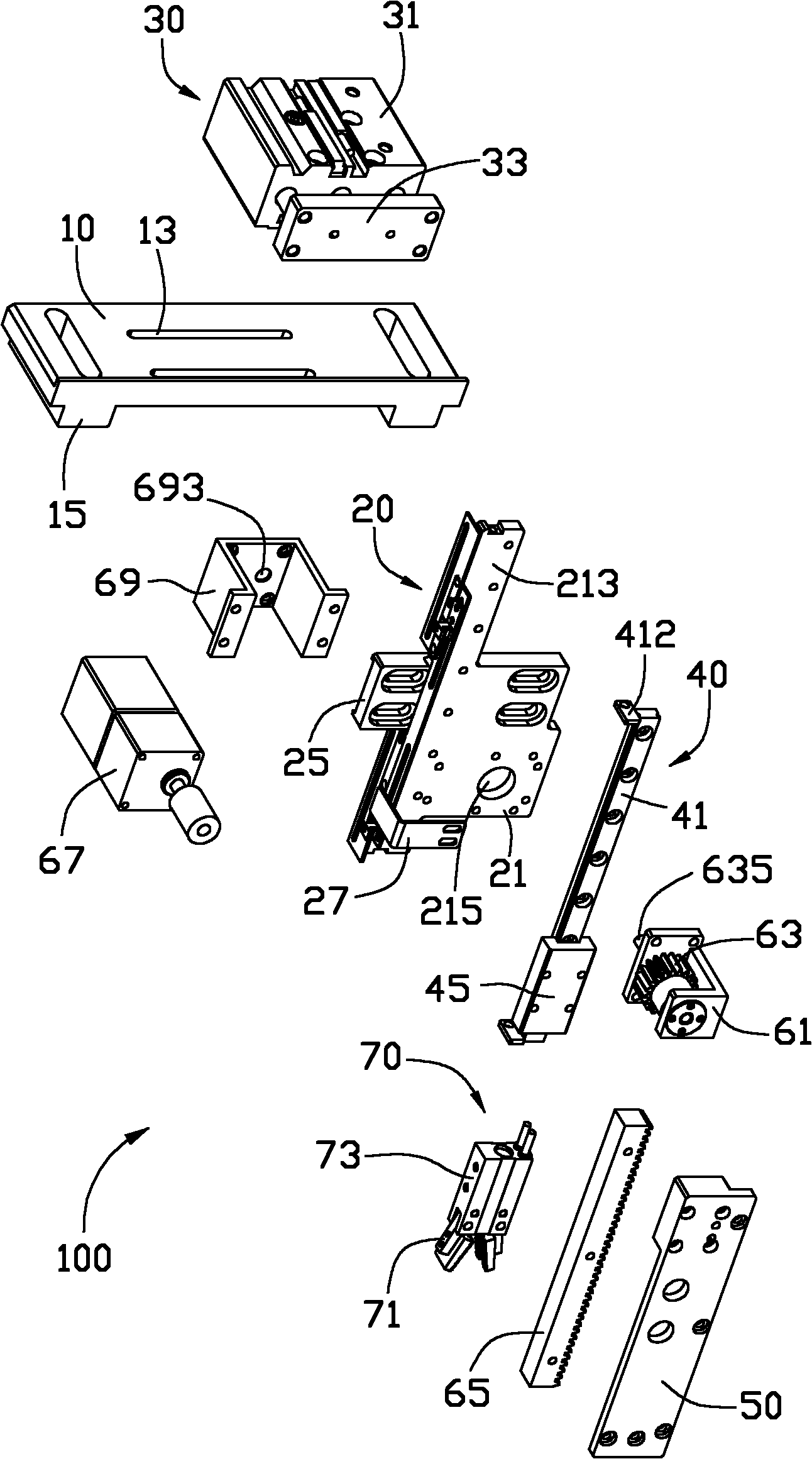
[0014] The manipulator gripping device 100 includes a support base 10 , a mounting frame 20 , an elevating driving device 30 , a sliding mechanism 40 , a connecting plate 50 , a horizontal driving device 60 and a jaw device 70 . The support base 10 is substantially perpendicular to the installation frame 20 . The installation frame 20 is driven by the lifting driving device 30 and is slidably installed with the support base 10 along a first direction (eg, vertical direction). The sliding mechanism 40 is installed on the mounting frame 20 and connected with the connecting plate 50, so that the connecting plate 50 and the mounting frame 20...


PUM


Abstract

The invention discloses a clamping device for a manipulator, and the clamping device comprises a supporting base, a mounting frame, a horizontal driving device and a clamping jaw device, wherein the mounting frame is arranged on the supporting base and can move relative to the supporting base along a vertical direction; the horizontal driving device comprises a base, a gear, a rack and a driving motor; the base is fixedly arranged on the mounting frame; the gear comprises a gear shaft; the gear is rotatably arranged on the base; the gear shaft extends out of the base and is connected to the driving motor; the rack is engaged with the gear; the gear is driven by the driving motor to cause the rack to horizontally slide relative to the gear; and the clamping jaw device is fixedly mounted on the rack and can slide relative to the mounting frame along with the rack in the horizontal direction.

Description

technical field [0001] The invention relates to a gripping device, in particular to a manipulator gripping device. Background technique [0002] Existing manipulators used on molding machines are generally bulky and heavy, inconvenient for installation, commissioning, and transportation, and have high energy consumption; it is not conducive to the improvement of production capacity and the development trend of energy conservation and emission reduction. Contents of the invention [0003] In view of this, it is necessary to provide a manipulator gripping device that is small in size and convenient in installation, commissioning and transportation. [0004] A manipulator gripping device, the manipulator gripping device includes a support base, a mounting frame, a horizontal drive device and a gripper device; Move; the horizontal driving device includes a base, a gear, a rack and a driving motor, the base is fixedly installed on the mounting frame, the gear includes a gear s...

Claims


Application Information

Patent Timeline
Patent Type & Authority Applications(China)
IPC IPC(8): B23Q7/00B25J9/08
CPCB29C45/42B29C2045/4266Y10T74/20305
Inventor 金建平张利华周科
Owner SHENZHEN FUTAIHONG PRECISION IND CO LTD
Why Eureka
Try Eureka