
Low oil return type piezoelectric control fuel injector

A fuel injector and piezoelectric technology, which is applied to machines/engines, fuel injection devices, engine components, etc., can solve the problem of reducing the lift rate of the injector needle valve, reducing the rate of pressure building in the control chamber, and decompressing the control chamber. Slow speed and other problems, to achieve the effect of saving compression work, speeding up pressure build-up and pressure relief rate, and improving fuel injection effect

Inactive Publication Date: 2012-03-14
HARBIN ENG UNIV
View PDF7 Cites 11 Cited by
  • Summary
  • Abstract
  • Description
  • Claims
  • Application Information

AI Technical Summary

Problems solved by technology

However, the existing piezoelectric injectors still have deficiencies, which need to be further optimized and improved: 1. When the injector is not injecting oil, the oil inlet hole and the oil discharge hole in the control chamber are connected, and a part of the high-pressure oil enters the control chamber and directly Released into the low-pressure fuel tank, wasting the compression work of this part of the fuel; 2: The fuel will heat up during the process of being compressed, and the temperature of the fuel in the fuel tank will rise after flowing back to the low-pressure fuel tank; 3: The process of opening the fuel injector In the process, due to the small diameter of the oil drain hole, the speed of pressure relief in the control chamber is very slow, resulting in a decrease in the lifting speed of the needle valve of the injector; Drain the oil, reduce the pressure building rate of the control chamber, and reduce the seating rate of the needle valve

Method used


Image

  • Low oil return type piezoelectric control fuel injector
  • Low oil return type piezoelectric control fuel injector
  • Low oil return type piezoelectric control fuel injector

Examples


Embodiment approach 1

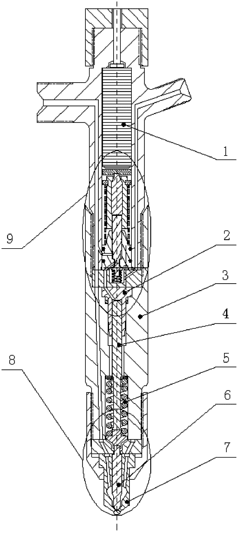
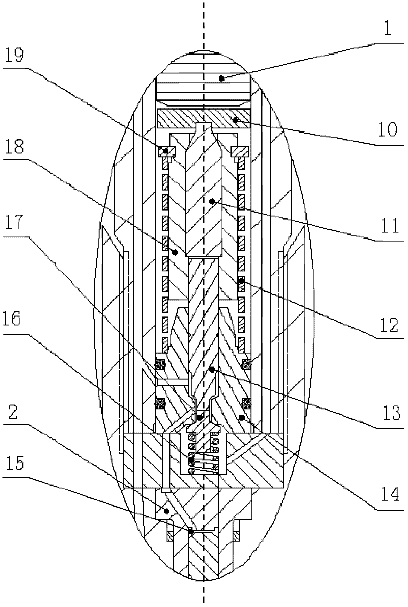
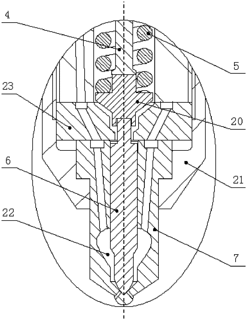
[0018] combine Figure 1~3 , the piezoelectric element 1, the hollow body 12, the conversion piston 11, the valve piston 13, the control valve 17, the return spring 16 and the control cavity 2 together constitute the piezoelectric control valve part 9 of the low oil return piezoelectric control injector . The piezoelectric element 1 manipulates the action and reset of the valve piston 13 and the control valve 17 by controlling the changing piston 11 , and the elastic metal gasket 10 can reduce the direct impact of the changing piston 11 on the piezoelectric element 1 . The changeover piston 11 and the valve piston 13 are collectively referred to as a hydraulic coupling, and are located in a housing 18 of the hydraulic coupling. The upper end of the hollow body 12 is stuck on the adjusting disc 19 of the hydraulic coupling housing 18, and the lower end is supported on the valve seat 14. The hollow body 12 is preloaded with pressure, which is transmitted to the hydraulic coupli...

Embodiment approach 2

[0022] combine Figure 4 , The inlet of the accumulator chamber 24 is connected with the high-pressure oil pipe, and the outlet is connected with the oil tank 22 and the oil inlet circuit of the control chamber 15. Piezoelectric element 1, hollow body 12, conversion piston 11, valve piston 13, control valve 17, return spring 16 and control cavity 2 together constitute the piezoelectric control valve part of the low oil return accumulator piezoelectric control injector 9. The piezoelectric element 1 manipulates the action and reset of the valve piston 13 and the control valve 17 by controlling the changing piston 11 , and the elastic metal gasket 10 can reduce the direct impact of the changing piston 11 on the piezoelectric element 1 . The changeover piston 11 and the valve piston 13 are collectively referred to as a hydraulic coupling, and are located in a housing 18 of the hydraulic coupling. The upper end of the hollow body 12 is stuck on the adjusting disc 19 of the hydra...


PUM


Abstract

The invention aims at providing a low oil return type piezoelectric control fuel injector, which comprises a piezoelectric element, a piezoelectric control valve part, a control piston, a needle valve reset spring and a fuel nozzle part that are arranged in a fuel injector body and connected in sequence, wherein the control piston is arranged in a control cavity body; the piezoelectric control valve part comprises a hydrodynamic coupler, a control valve and a reset spring which are connected in sequence, wherein the hydrodynamic coupler comprises a hydrodynamic coupler shell, a transform piston, a valve piston, an adjusting disc, a hollow body and a valve seat; the transform piston and the valve piston are connected and are both arranged in the hydrodynamic coupler shell; the hollow body and the adjusting disc are arranged on the hydrodynamic coupler shell; the upper end of the hollow body is blocked on the adjusting disc; the lower end of the hollow body is supported on the valve seat; and a control cavity is arranged above the control piston. The low oil return type piezoelectric control fuel injector can prevent high-pressure fuel oil from directly discharging to a low-pressure oil path, thereby reducing the oil return amount, saving the compression work of an oil-fired oil pump and reducing the temperature rise of an oil tank.

Description

technical field [0001] The invention relates to a fuel injector of an engine fuel injection system. Background technique [0002] In recent years, the technology of electronically controlled fuel injectors for diesel engines has developed rapidly, and the application of electronically controlled fuel injectors has become an inevitable trend in the development of diesel engines. Due to the fast response characteristics of the piezoelectric control element, it is possible to quickly and accurately control the fuel injection quantity and injection law of the diesel engine, so as to achieve the purpose of improving the economy, power and reducing harmful emissions of the diesel engine. [0003] The currently applied piezoelectric control injector divides the high-pressure fuel from the high-pressure fuel pipe into two paths: one path enters the fuel tank below the needle valve of the injector, and the other path enters the control chamber above the control piston. When the piez...

Claims


Application Information

Patent Timeline
IPC IPC(8): F02M51/06F02M61/16
Inventor 范立云王昊田丙奇马修真李清赵文圣李鹏豪
Owner HARBIN ENG UNIV
Learn More