Relay node non-access stratum processing method and equipment

A technology of relay nodes and processing methods, which is applied in the field of non-access layer process processing, and can solve problems such as not being able to know the support status of the network side

Active Publication Date: 2012-03-14
DATANG MOBILE COMM EQUIP CO LTD
View PDF4 Cites 16 Cited by
  • Summary
  • Abstract
  • Description
  • Claims
  • Application Information

AI Technical Summary

Problems solved by technology

[0015] The disadvantage of the existing technology is that the RN cannot know the support situation of the

Method used


Image

  • Relay node non-access stratum processing method and equipment
  • Relay node non-access stratum processing method and equipment
  • Relay node non-access stratum processing method and equipment

Examples


Embodiment 1

[0126] In this embodiment, a NAS message is used for notification, and the establishment of a dedicated bearer is initiated after the RN downloads the OAM. Figure 5 It is a schematic diagram of the implementation flow of the RN startup process in Embodiment 1, as shown in the figure, which may include the following steps:

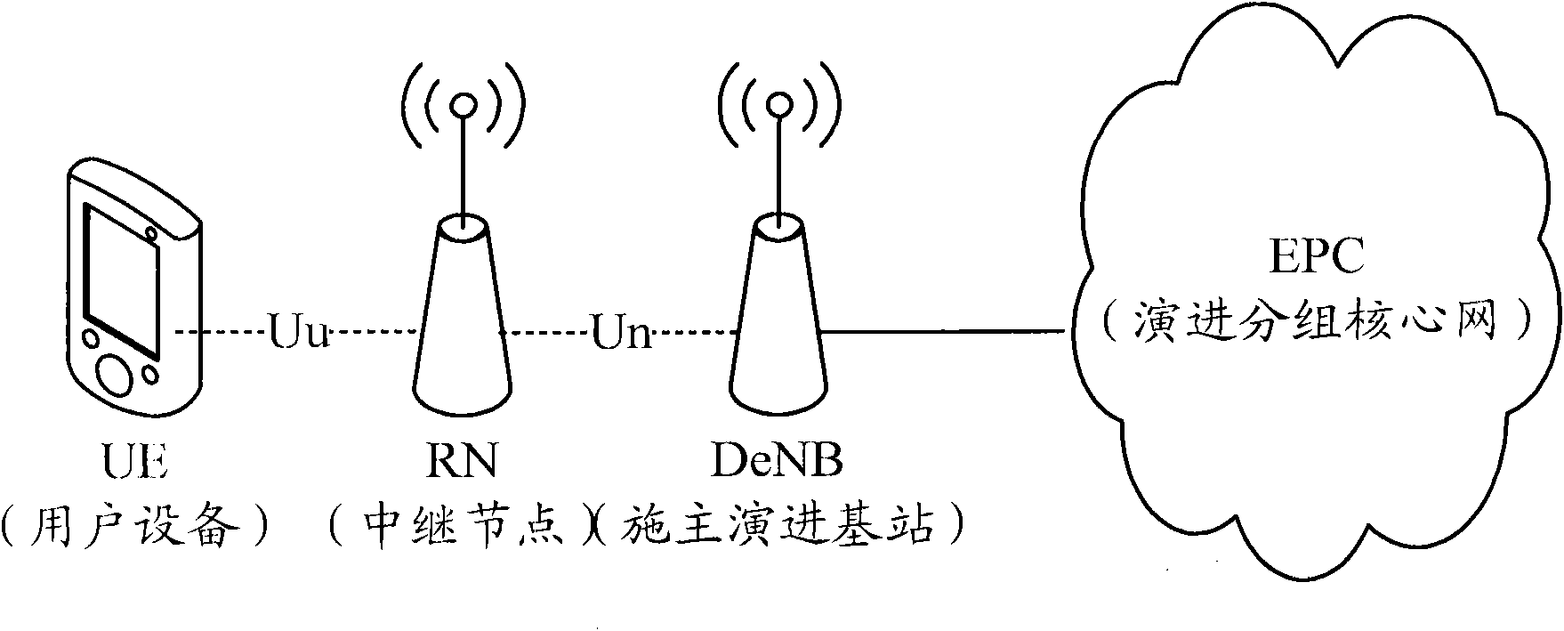
[0127] In step 501, the RN starts up and establishes an RRC bearer with the DeNB.

[0128] In step 502, the DeNB selects an MME for the RN, and sends an initial UE message (Initial UEMessage) to it.

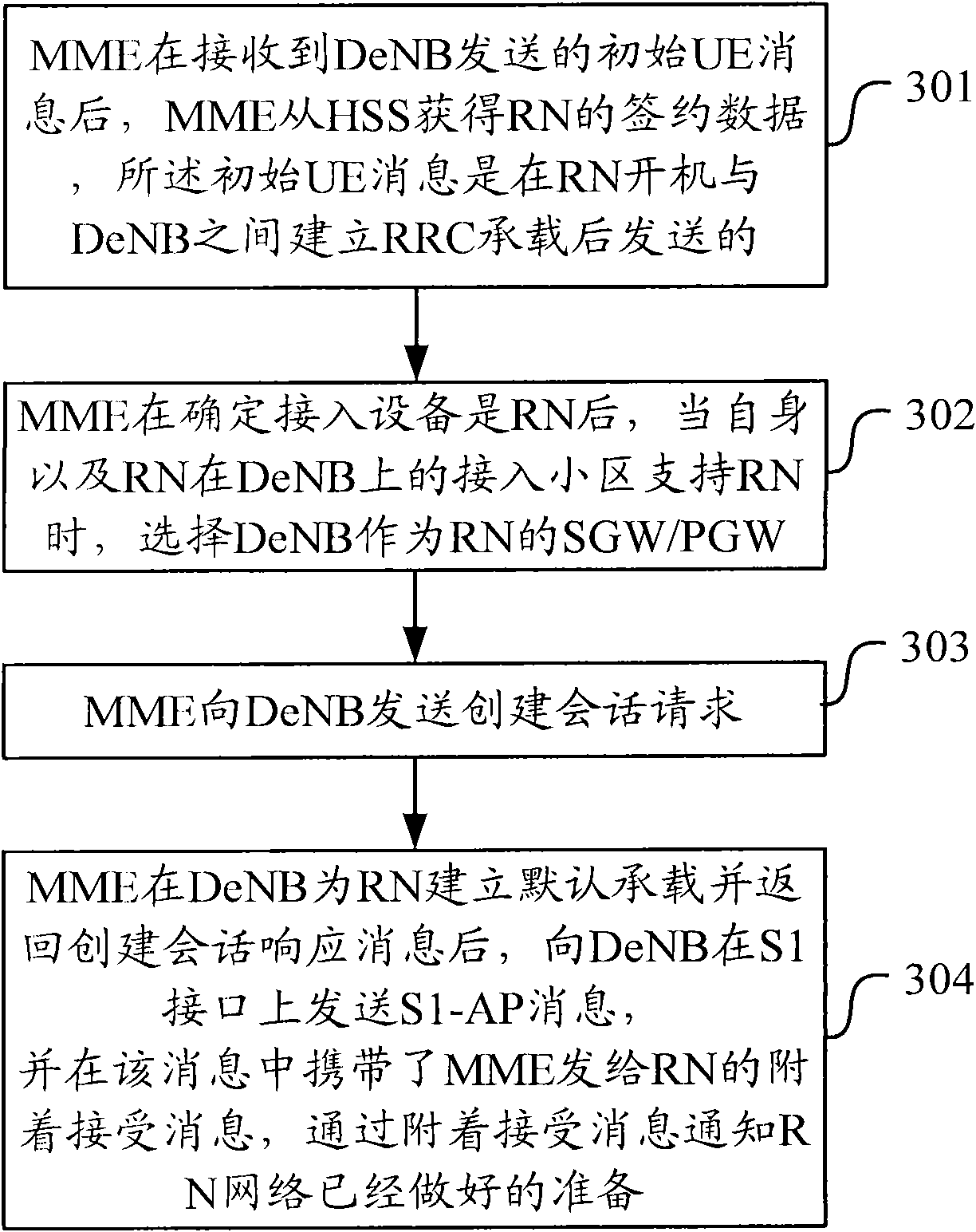
[0129] Step 503-Step 505, security authentication is performed between the network and the RN. If the authentication is passed, the MME obtains information such as the subscription data of the RN from the HSS.

[0130] Step 506-Step 507, if the selected MME supports RN, then the MME judges the access entity type and the access cell type. If it is known that the access entity is RN and the current serving base station is DeNB, select DeNB as the SGW / PGW of ...

Embodiment 2

[0149] In this embodiment, a NAS message is used for notification, and a dedicated bearer is established before the RN downloads the OAM.

[0150] Change the order of the processing of step 512 and RN in Embodiment 1:

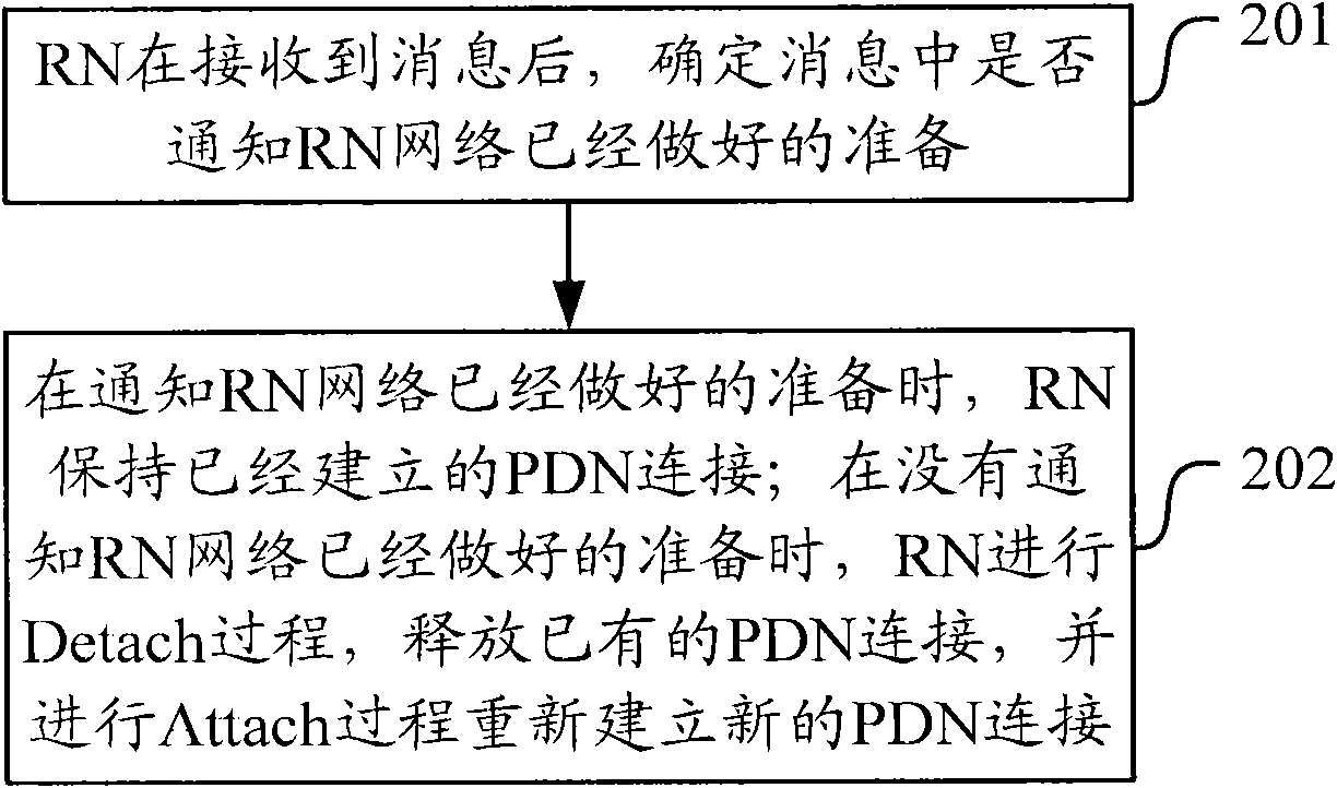
[0151] If the RN receives the indication of "the network is ready" from the NAS message, the RN can maintain the established PDN connection. If necessary, a request can be made to the network side to establish a dedicated bearer.

[0152] If the RN does not receive the indication of "the network is ready", after the RN detach from the network side, it selects an eNB that can serve as a DeNB for access, and reattaches.

[0153] RN downloads configuration data from OAM. Then establish the necessary S1 interface and X2 interface, and you are ready to work.

[0154]The implementation of other steps can refer to embodiment 1.

Embodiment 3

[0156] In this embodiment, the NAS message is used for notification, and the process of establishing a dedicated bearer is initiated by the DeNB.

[0157] For the above implementation, reference may be made to steps 501-505 of Embodiment 1. That is, the RN starts up and establishes an RRC bearer with the DeNB. The DeNB selects an MME for the RN, and sends the initial UE message to it. Security authentication is performed between the network and the RN. If the authentication is passed, the MME obtains information such as the subscription data of the RN from the HSS.

[0158] If the selected MME supports RN, then the MME judges the type of the access entity and the type of the cell to be accessed. After learning that the access entity is the RN and the current serving base station is the DeNB, select the DeNB as the SGW / PGW of the RN; then, the MME sends a session creation request to the DeNB, and establishes a default bearer for the RN in the DeNB. In the session creation r...


PUM


Abstract

The invention discloses a relay node non-access stratum processing method and equipment. The method comprises the steps that after access equipment is determined to be a relay node by a mobility management entity, when the access cell of the mobility management entity and the relay node on an evolved node B supports the relay node, the evolved node B is informed about that a network has been already prepared; after the evolved node B is determined to be selected as a serving gateway/packet data network gateway for the relay node, an indication that the network has been already prepared is transmitted to the relay node; when the relay node is informed about that the network has been already prepared, the relay node keeps the built connection with a packet data network; and when the relay node is not informed about that the network has been already prepared, the relay node conducts a detaching process to release the existing connection with the packet data network and conducts an attaching process to rebuild new connection with the packet data network. The relay node non-access stratum processing method and the equipment have the advantages that the starting process of the relay node can be simplified, the starting time of the relay node is shortened and the unnecessary signaling process and bearer management are reduced.

Description

technical field [0001] The invention relates to mobile communication technology, in particular to a non-access stratum process processing method and equipment of a relay node. Background technique [0002] In future mobile communication systems, such as B3G (Beyond Third Generation) or LTE-A (Long Term Evolution-Advanced, long-term evolution upgrade), the system will provide higher peak data rate and cell throughput, and also Larger bandwidth is needed. At present, there is very little unallocated bandwidth below 2GHz. Part or all of the bandwidth required by the B3G system can only be found in higher frequency bands, such as above 3GHz. The higher the frequency band, the faster the attenuation of radio wave propagation and the shorter the transmission distance. Therefore, in the same coverage area, to ensure continuous coverage, more base stations are required. Since base stations usually have a higher cost, this will undoubtedly increase the cost of network deployment. In...

Claims


Application Information

Patent Timeline
IPC IPC(8): H04W76/02H04W92/04
Inventor 杨义
Owner DATANG MOBILE COMM EQUIP CO LTD
Why Eureka
Try Eureka