Control system for internal combustion engine

A technology for control systems and internal combustion engines, applied in engine control, fuel injection control, internal combustion piston engines, etc., can solve problems such as different intake air volume, reduced combustion stability, and increased exhaust emissions

Inactive Publication Date: 2014-05-14
TOYOTA JIDOSHA KK
View PDF6 Cites 0 Cited by
  • Summary
  • Abstract
  • Description
  • Claims
  • Application Information

AI Technical Summary

Problems solved by technology

[0008] However, when the injection ratio of the first fuel injection valve and the second fuel injection valve changes in transition, the intake air amount obtained by the air flow meter or the like may differ from the actual intake air amount.
[0009] In the above cases, if the control parameters such as the fuel injection amount are determined based on the obtained value of the intake air amount, it may lead to a decrease in combustion stability and an increase in exhaust emissions.

Method used


Image

  • Control system for internal combustion engine
  • Control system for internal combustion engine
  • Control system for internal combustion engine

Examples


Embodiment 1

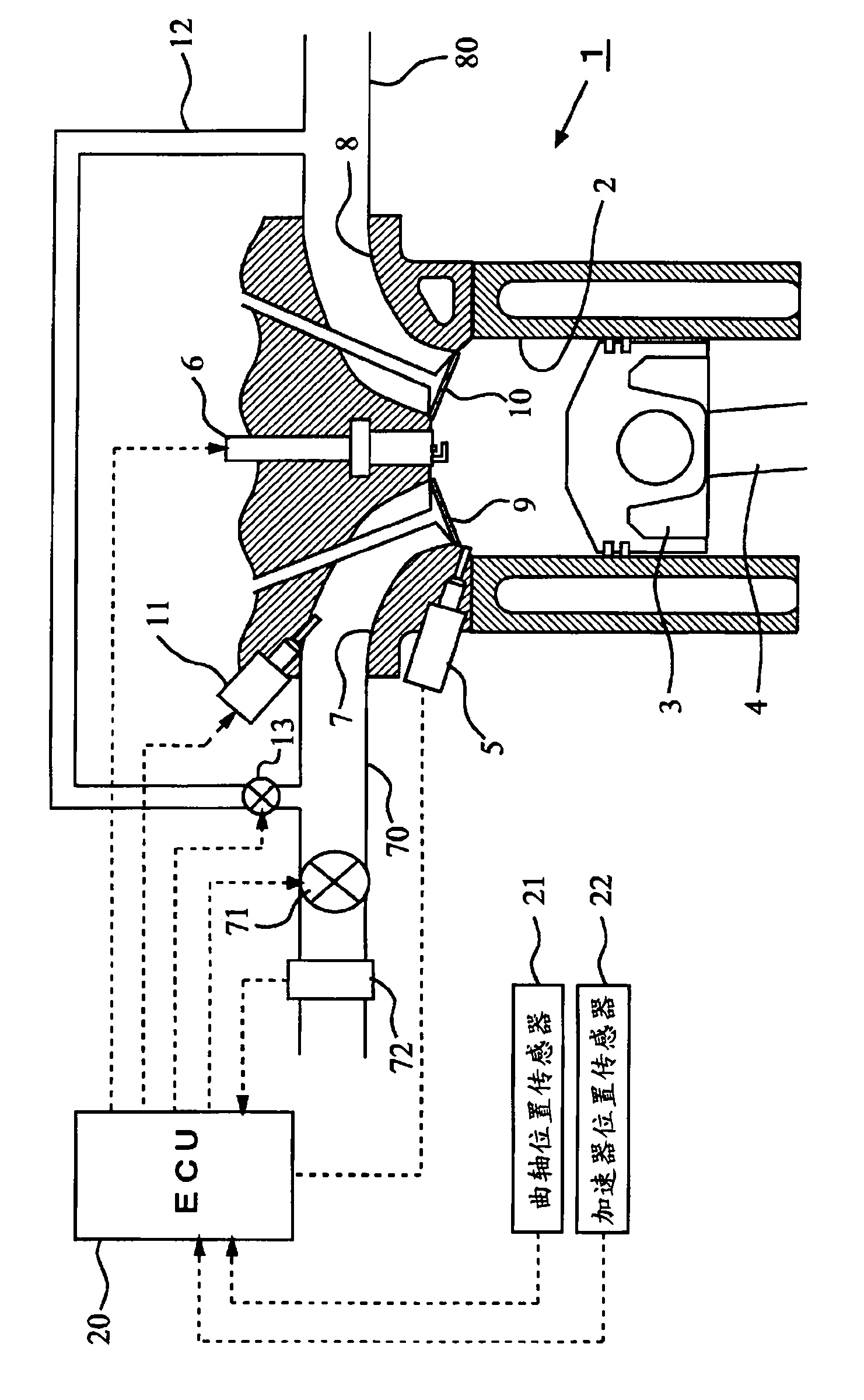
[0053] First, based on Figure 1 to Figure 10 A first embodiment of the present invention will be described. figure 1 is a diagram showing a schematic configuration of an internal combustion engine to which the present invention is applied.

[0054] figure 1 The shown internal combustion engine 1 is a 4-stroke cycle spark ignition internal combustion engine (gasoline engine) having a plurality of cylinders. Among them, in figure 1 In represents only 1 cylinder among the plurality of cylinders.

[0055] A piston 3 is slidably housed in each cylinder 2 of the internal combustion engine 1 . The piston 3 is connected to an unillustrated output shaft (crankshaft) via a connecting rod 4 . Furthermore, a first fuel injection valve 5 for injecting fuel into the cylinder and an ignition plug 6 for igniting the air-fuel mixture in the cylinder are attached to each cylinder 2 .

[0056] The inside of the cylinder 2 communicates with an intake port 7 and an exhaust port 8 . An open...

Embodiment 2

[0094] Next, based on Figure 11 A second embodiment of the present invention will be described. Here, configurations different from those of the aforementioned first embodiment will be described, and descriptions of the same configurations will be omitted.

[0095] In the aforementioned first embodiment, an example was described in which the detection value of the air flow meter 72 is corrected when the in-cylinder injection ratio changes transitionally. However, in this embodiment, when the in-cylinder injection ratio and This is an example of correcting the detection value of the air flow meter 72 at the transient time when the opening degree of the EGR valve 13 is changed.

[0096] For example, when the operating state of the internal combustion engine 1 shifts from the EGR non-operating region to the EGR operating region, the actual opening degree of the EGR valve 13 does not immediately converge to the target EGR valve opening degree. In addition, since the EGR gas tra...


PUM


Abstract

The present invention has an object to obtain an accurate amount of intake air at the time of an operation of an EGR mechanism in a control system of an internal combustion engine which is provided with a first fuel injection valve for injecting fuel into a cylinder, a second fuel injection valve for injecting fuel into an intake port, and the EGR mechanism. In order to achieve this object, the present invention resides in a control system of an internal combustion engine which is provided with a first fuel injection valve that injects fuel into a cylinder of the internal combustion engine, a second fuel injection valve that injects fuel into an intake port of the internal combustion engine, an EGR passage that introduces an EGR gas from an exhaust passage of the internal combustion engine to an intake passage thereof, an EGR valve that is arranged in the EGR passage, and an obtaining means that obtains an amount of intake air in the internal combustion engine, wherein when the EGR valve is open, a determination is made based on a value of a cylinder injection ratio, as to whether the amount of intake air is in an increasing tendency or in a decreasing tendency with respect to a change in the cylinder injection ratio, and a value of the amount of intake air thus obtained is corrected according to a result of the determination.

Description

technical field [0001] The present invention relates to a control system for an internal combustion engine including a fuel injection valve injecting fuel into a cylinder and a fuel injection valve injecting fuel into an intake port. Background technique [0002] Patent Document 1 describes a technology that, in an internal combustion engine provided with a first fuel injection valve that injects fuel into a cylinder and a second fuel injection valve that injects fuel into an intake port, when the engine speed is low, by increasing The injection ratio of the first fuel injection valve and the second fuel injection valve improves the filling efficiency of the intake air. [0003] Patent Document 2 describes a technique for cooling intake air in a cylinder by reducing the amount of fuel injected from the fuel injection valve per unit time in an internal combustion engine including a fuel injection valve injecting fuel into the cylinder. [0004] Patent Document 3 describes a ...

Claims


Application Information

Patent Timeline
Patent Type & Authority Patents(China)
IPC IPC(8): F02D41/04F02D21/08F02D41/34F02D45/00F02M63/00
CPCF02D11/10F02B23/104F02D41/3094F02D41/402F02D41/0072Y02T10/47F02D41/182F02D41/0047F02M69/046F02D41/0057F02M25/0786F02M26/64Y02T10/40
Inventor 北东宏之品川知广佐竹信行
Owner TOYOTA JIDOSHA KK
Why Eureka
Try Eureka