
Composite cutter

A technology of composite cutting tools and cutting tools, which is used in drilling tool accessories, manufacturing tools, drilling/drilling equipment, etc. High pass rate, convenient replacement, and the effect of improving work efficiency

Inactive Publication Date: 2012-03-21
徐美芳
View PDF0 Cites 3 Cited by
  • Summary
  • Abstract
  • Description
  • Claims
  • Application Information

AI Technical Summary

Problems solved by technology

The process steps of its processing are generally drilling first, then reaming and reaming. Each step of the process needs to be replaced with different tools. Therefore, the coaxiality of the processed holes is not very high.
The processing of high-precision holes generally requires the use of compound tools. The current method of fixing the compound tool to the machine tool is relatively complicated and inconvenient to replace.

Method used


Image

  • Composite cutter
  • Composite cutter

Examples


Embodiment Construction

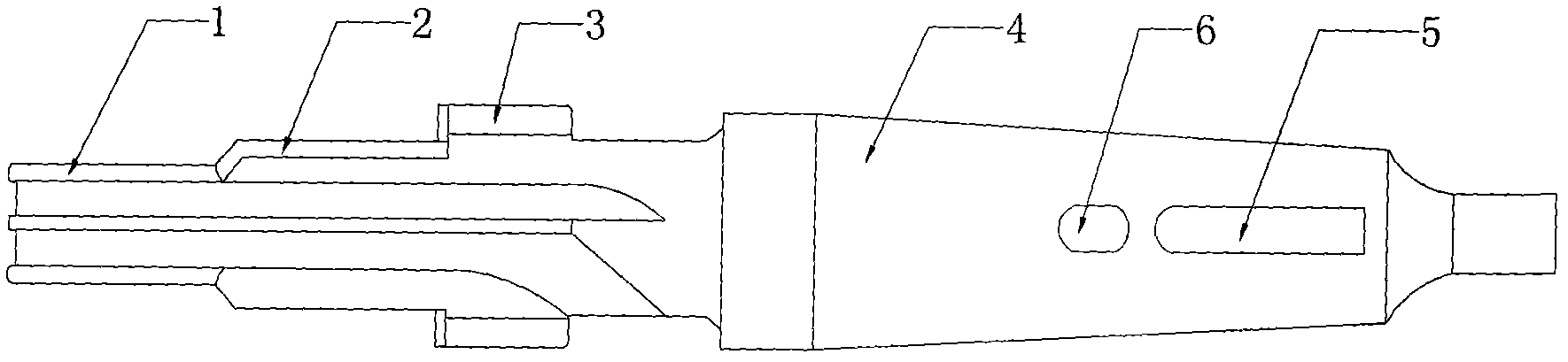
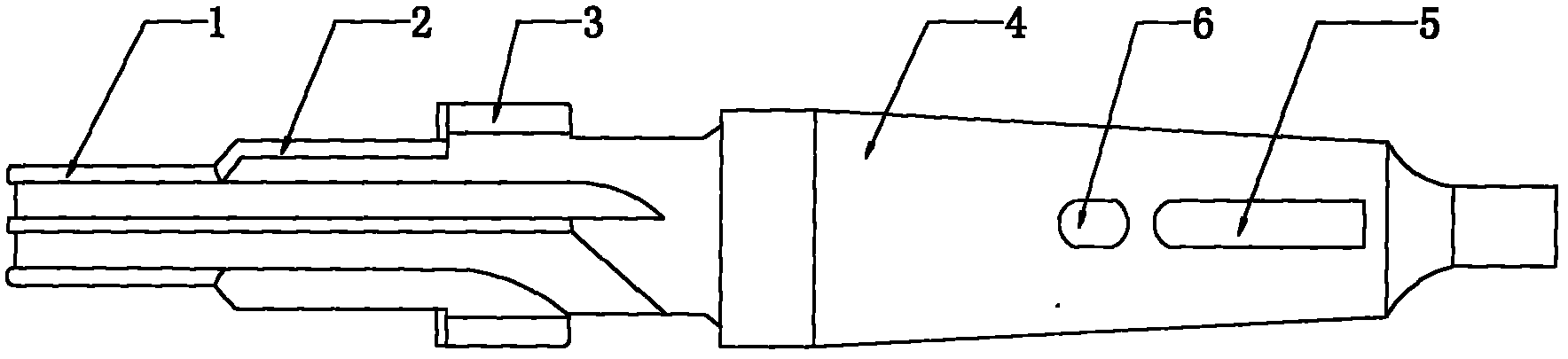
[0011] like figure 1 As shown, a compound tool is composed of a drill 1, a reamer 2, a countersink 3 and a handle 4, so that the tool can simultaneously perform drilling, reaming and hole end processing, and is formed at one time. For the production of cutting tools, the drilling tool 1, reamer 2 and countersinking tool 3 are designed as an integrated structure. In order to improve the stability and convenience of fixing the tool and the machine tool, a keyway 5 and a positioning groove 6 are set on the tool handle 4. Further, the handle 4 is designed into a tapered structure.


PUM


Abstract

The invention relates to a composite cutter. The composite cutter is characterized by consisting of a driller, a reamer, a spot facer and a cutter handle, wherein the cutter handle is provided with a key groove; the driller, the reamer and the spot facer are of an integrated structure; and the cutter handle is also provided with a positioning groove. In the composite cutter, the concentricity and the qualification rate of machined holes are high, the cost can be greatly reduced, the working efficiency is improved, the stability is strong and the replacement is convenient.

Description

technical field [0001] The invention relates to a compound cutting tool, which belongs to the field of non-standard cutting tools. Background technique [0002] In machining, the machining of holes is the most common. The process steps of its processing are generally drilling first, then reaming and reaming. Each step of the process needs to be replaced with different tools. Therefore, the coaxiality of the processed holes is not very high. The processing of high-precision holes generally requires the use of compound tools. The current method of fixing the compound tool to the machine tool is relatively complicated and inconvenient to replace. Contents of the invention [0003] The object of the present invention is to provide a compound cutter, which can perform drilling, reaming and hole end face processing at the same time, and can be formed at one time. [0004] The technical scheme adopted in the present invention is: [0005] A composite cutter, the cutter is comp...

Claims


Application Information

Patent Timeline
Patent Type & Authority Applications(China)
IPC IPC(8): B23B51/08
Inventor 徐美芳
Owner 徐美芳
Learn More