Multi-axis linkage mechanical device used for finely repairing micro-defects on surface of optical element

A technology of optical components and multi-axis linkage, which is applied in the direction of working accessories, stone processing tools, manufacturing tools, etc.

Active Publication Date: 2012-03-21
HARBIN INST OF TECH
View PDF7 Cites 20 Cited by
  • Summary
  • Abstract
  • Description
  • Claims
  • Application Information

AI Technical Summary

Problems solved by technology

[0040] The purpose of the present invention is to solve the problem of the growth of micro-defects generated in the process of high-energy beam intensity laser

Method used


Image

  • Multi-axis linkage mechanical device used for finely repairing micro-defects on surface of optical element
  • Multi-axis linkage mechanical device used for finely repairing micro-defects on surface of optical element
  • Multi-axis linkage mechanical device used for finely repairing micro-defects on surface of optical element

Examples


specific Embodiment approach 1

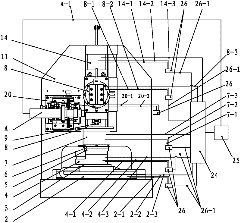
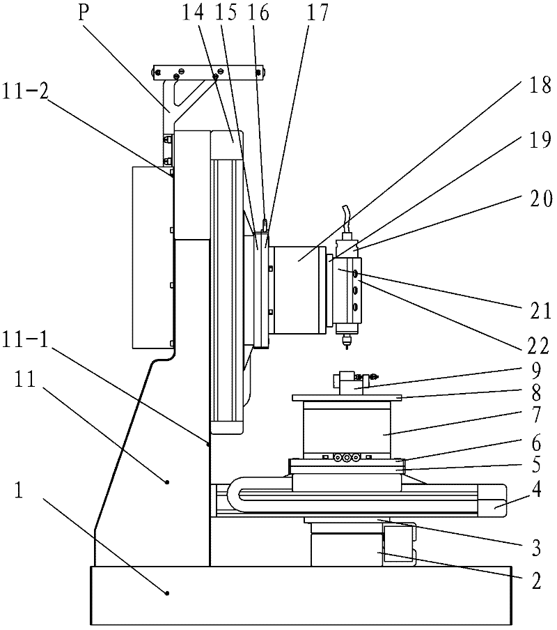
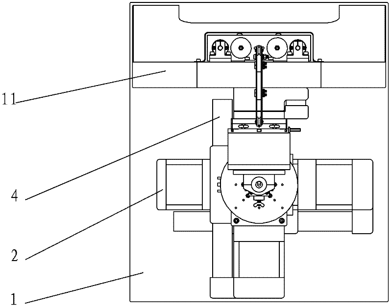
[0044] Specific implementation mode one: combine Figure 1 to Figure 11 Describe this embodiment. The multi-axis linkage mechanical device for micro-repair of micro-defects on the surface of optical elements in this embodiment includes a flat plate base 1, an X-axis linear unit 2, an XY-axis linear unit connector 3, a Y-axis linear unit 4, and a YC-axis first Connector 5, YC-axis second connector 6, C-axis rotation unit 7, workbench 8, chuck body 9, CCD tool setting and monitoring device A, vertical member 11, Z-axis linear unit 14, ZB-axis first connection Part 15, ZB axis second connecting part 17, B-axis rotating unit 18, main shaft part connecting part 19, electric main shaft 20, main shaft first pressing part 21 and main shaft second pressing part 22, ball end milling cutter 23, multiple Axis controller 24, host computer 25 and six drivers 26, vertical member 11 is vertically installed on the flat base 1, and X-axis linear unit 2 is also installed on the flat base 1, and ...

specific Embodiment approach 2

[0064] Specific implementation mode two: combination Figure 1 to Figure 3 To illustrate this embodiment, the flat base 1 and the vertical member 11 of this embodiment are both made of granite. With such arrangement, the dynamic performance of the whole device can be improved because the granite has a good shock-absorbing performance. Other compositions and connections are the same as in the first embodiment.

specific Embodiment approach 3

[0065] Specific implementation mode three: combination Figure 1 to Figure 3 The present embodiment will be described. The shaft hole interference fit is used between the table 8 and the C-axis rotation unit 7 in the present embodiment. Such setting ensures that the axis of the worktable 8 coincides with the rotation axis of the C-axis rotation unit 7 . Other compositions and connections are the same as those in Embodiment 1 or Embodiment 2.


PUM


Abstract

The invention provides a multi-axis linkage mechanical device used for finely repairing micro-defects on a surface of an optical element and relates to a mechanical device for repairing the optical element. The mechanical device is used for solving the problem of the growth of micro-defects generated during a high-energy beam intense laser targeting process of the optical element. A vertical element is vertically mounted on a plate base; an X-axis linear unit is mounted on the plate base; the X-axis linear unit is connected with a Y-axis linear unit through an XY linear unit connector; the Y-axis linear unit is connected to a C-axis rotating unit through two connectors; an operating platform is mounted on the C-axis rotating unit; a fixture body is mounted on the operating platform; a Z-axis linear unit is mounted on the vertical element; the Z-axis linear unit is connected to a B-axis rotating unit through two connectors; a spindle connector is mounted on the B-axis rotating unit; an electric spindle clamping fixture is mounted between a first spindle clamping element and a second spindle clamping element; and a CCD (Charge Coupled Device) tool setter and a monitoring device are mounted on a main mounting surface of the vertical element. The multi-axis linkage mechanical device is used for repairing the surface of the optical element.

Description

technical field [0001] The invention relates to a mechanical device for repairing an optical element, in particular to a multi-axis linkage mechanical device for repairing micro-defects on the surface of an optical element. Background technique [0002] At this stage, in the controlled confinement nuclear fusion ignition project, high-precision fused silica, KDP crystal and other optical components play a very important role in it. For example, KDP crystal, as a crystal material for Pockels cell (Pockels) and optical frequency doubling conversion, is currently the only candidate material that cannot be replaced. How to achieve high precision and high surface quality processing of optical components, and improve the performance and service life of such optical components in nuclear fusion devices is very important. For optical components such as fused silica and KDP crystal, during the processing and under the action of high-energy laser beam targeting, micro-defects with ch...

Claims


Application Information

Patent Timeline
IPC IPC(8): B28D1/18B28D7/00
Inventor 陈明君肖勇吴春亚田文兰倪海波郑庭姜艳
Owner HARBIN INST OF TECH
Why Eureka
Try Eureka