Comprehensive environmental control/liquid cold and heat energy management system for non-stamping air inlet duct

A management system, cold and heat energy technology, applied in the direction of air handling equipment, energy-saving board measures, aircraft parts, etc., can solve the increase of compensatory loss of refrigeration system performance, insufficient utilization of refrigeration system refrigeration capacity, reduction of aircraft fuel and flight performance, etc. problems, to achieve the effect of reducing performance compensation loss, improving water removal and refrigeration efficiency, and reducing impact

Active Publication Date: 2012-03-21
XIAN AIRCRAFT DESIGN INST OF AVIATION IND OF CHINA
View PDF6 Cites 18 Cited by
  • Summary
  • Abstract
  • Description
  • Claims
  • Application Information

AI Technical Summary

Problems solved by technology

These two refrigeration systems both use air-to-air heat exchangers or air-to-liquid heat exchangers to transfer the heat load of the cockpit or electronic equipment to the outside atmosphere, which will lead to an increase in the compensatory loss of the performance of the refrigeration system and an increase in the flight resistance of the aircraft. and reduced flight performance
[0004] On the other hand, as the flight altitude increases, the cooling load of the environmental control system becomes smaller and the heating load becomes larger, and the thermal load of large electronic equipment is in a full-power working state at high altitude, which requires the largest cooling capacity. The explanation is simple The 1+1 has the problem of insufficient utilization of the cooling capacity of the refrigeration system, indicating that the current system design does not consider the feasibility of using part of the cooling capacity of the liquid cooling system to cool the air of the environmental control system as the flight altitude increases

Method used


Image

  • Comprehensive environmental control/liquid cold and heat energy management system for non-stamping air inlet duct
  • Comprehensive environmental control/liquid cold and heat energy management system for non-stamping air inlet duct

Examples


Embodiment Construction

[0020] The present invention will be further described below by means of specific embodiments:

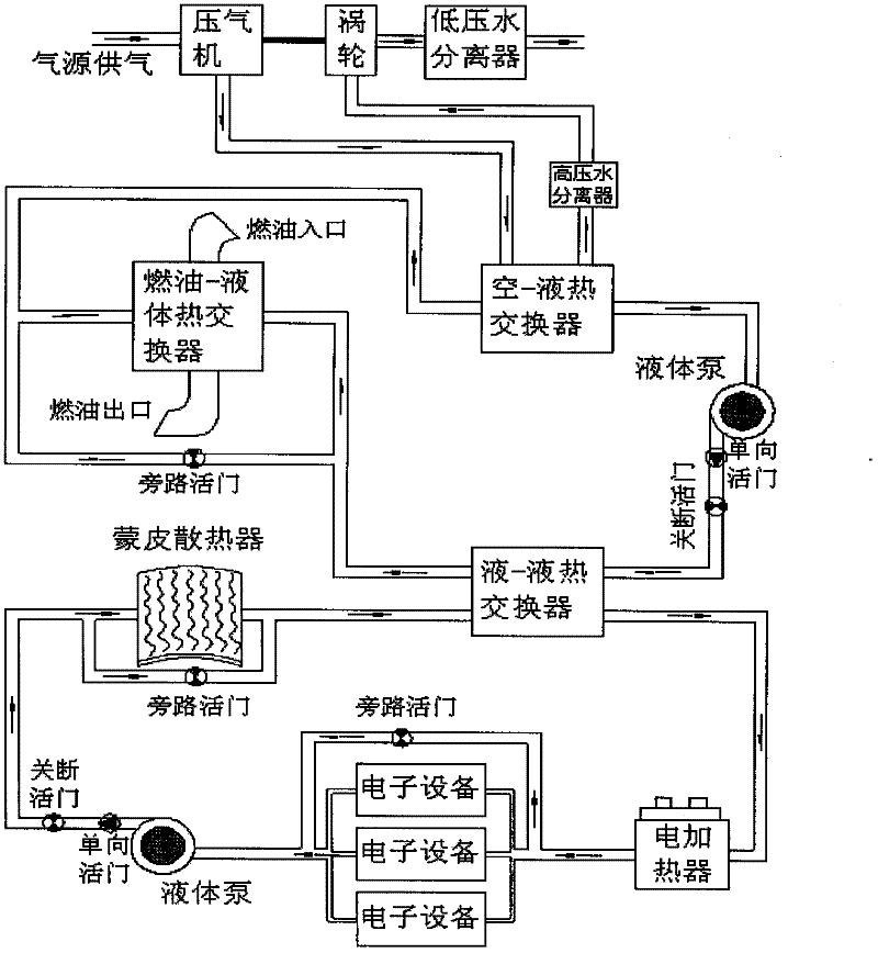
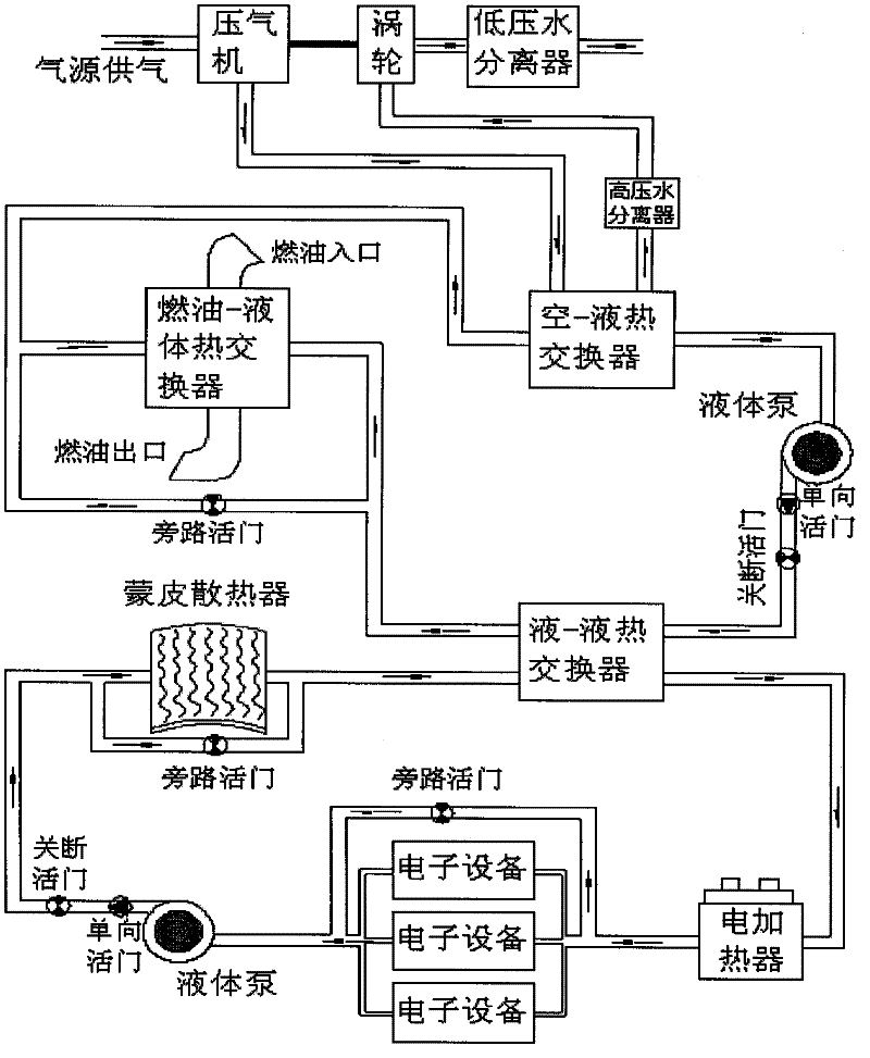
[0021] In the actual working process of the comprehensive environmental control / liquid-cooled thermal management system without ram inlet, the high-pressure and high-temperature air from the air source system is first compressed by the compressor to increase the temperature and pressure, and then cooled by the air-liquid heat exchanger. The free water is separated through the high-pressure water separator, and then the turbine expands and cools down to a lower temperature, and then the free water in the air is further separated through the low-pressure water separator. The outlet air temperature can generally reach -10°C or even lower.

[0022] The liquid cooling system 1 coupled with the refrigeration component of the environmental control system is driven by a liquid pump to flow resistance, passing through the one-way valve and the shut-off valve in sequence, then passing through...


PUM


Abstract

The invention relates to a comprehensive environmental control / liquid cold and heat energy management system for a non-stamping air inlet duct, belonging to the field of aircraft-mounted equipment and in particular relating to an improved comprehensive environmental control / liquid cold and heat energy management system for the non-stamping air inlet duct. The system is composed of four parts of a two-wheel type high pressure water-removing refrigerating assembly, a liquid cooling system 1, a liquid cooling system 2 and a fuel oil system, wherein the high pressure water-removing refrigerating assembly and the liquid cooling system 1 are coupled through an air-liquid heat exchanger; and the air-liquid heat exchanger is located at the downstream of an air compressor outlet in the two-wheel type high pressure water-removing refrigerating assembly and is located between a fuel oil-liquid heat exchanger and a liquid pump in the liquid cooling system. The system reduces the compensation loss of the refrigerating system property, improves the water-removing and refrigerating efficiency of the refrigerating assembly, effectively reduces the influence on the flight performance of an aircraft, enhances the fuel oil efficiency of the aircraft and has good aircraft economy.

Description

technical field [0001] The invention belongs to the field of aircraft airborne equipment, and in particular relates to the improvement of a comprehensive environment control / liquid cooling thermal energy management system for a non-ramming air inlet. Background technique [0002] The shortcomings of current technology are mainly manifested in the following aspects: [0003] On the one hand, the refrigeration systems currently used on aircraft mainly include air circulation-based environmental control systems and liquid circulation-based liquid cooling systems. The former is generally used for ventilation and cooling of cockpits and electronic equipment, while the latter is mainly used for electronic equipment with large thermal loads. cooling. These two refrigeration systems both use air-to-air heat exchangers or air-to-liquid heat exchangers to transfer the heat load of the cockpit or electronic equipment to the outside atmosphere, which will lead to an increase in the com...

Claims


Application Information

Patent Timeline
Patent Type & Authority Applications(China)
IPC IPC(8): B64D13/08
CPCY02T50/50
Inventor 党晓民成杰
Owner XIAN AIRCRAFT DESIGN INST OF AVIATION IND OF CHINA
Why Eureka
Try Eureka