Suction sewage truck for railway ballast bed

A technology for sewage suction vehicles and track beds, which is used in track cleaning, construction, cleaning methods, etc., can solve the problems of limited track suction width, reduced sewage suction capacity, large distance, etc., to improve space utilization and dynamic performance. The effect of improving dirt absorption performance and reducing manufacturing cost

Active Publication Date: 2012-03-21
CRCC HIGH TECH EQUIP CORP LTD
View PDF8 Cites 26 Cited by
  • Summary
  • Abstract
  • Description
  • Claims
  • Application Information

AI Technical Summary

Problems solved by technology

However, the car has the following deficiencies: First, the distance between the blowing and suction hood (sewage suction port) and the surface of the track is relatively large, resulting in insufficient suction capacity, especially the inability to absorb dirt with a large proportion such as iron powder produced by rail grinding. This is because the existing sewage suction device is integrally fixed on the sewage suction vehicle. In order to ensure the driving safety of the train, the lower end of the blowing and suction cover can only be fixedly arranged in a certain distance above the rail, so that the sewage suction port and the ballast bed The distance between the surfaces is too large, which reduces the suction capacity
The second is that the sewage suction device is fixed as a whole and cannot exceed the limit of the vehicle, so that the width of the track’s sewage suction is very limited, and it cannot clean the dirt on the two outer ends of the track and the emergency passages in the tunnel and the cable trenches, resulting in the railway track bed. Dirty blind spots are not conducive to the safe running of high-speed trains

Method used


Image

  • Suction sewage truck for railway ballast bed
  • Suction sewage truck for railway ballast bed
  • Suction sewage truck for railway ballast bed

Examples


Embodiment Construction

[0028] The present invention will be further described below in conjunction with the drawings.

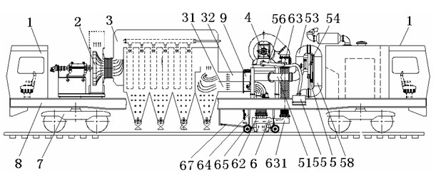
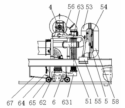
[0029] The railway track bed sewage suction vehicle provided by the present invention includes a bogie 7 underneath, a cab 1, a conventional dust collector 3 and an exhaust fan 2, and a conventional blower 4 frame 8 on the frame 8. There are a lifting type railway track bed pollution blowing and suction device 6 connected with the dust collector 3 and a railway track bed side pollution blowing and suction device 5, of which:

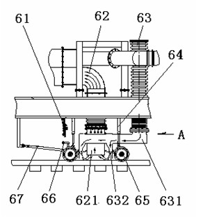
[0030] The lifting type railway track bed blowing and suction device 6 includes a suction bellows 62 connected to the inlet 31 of the dust collector 3 through a damper 9, a blowing bellows 63 connected to the blower 4, and a lifting cylinder 64 connected to the train On the lower side of the frame 8 there is a movable frame 66 with guide wheels 65 on it. The movable frame 66 is provided with a blow box 632 whose upper end is connected to the blowing bellows 62 and...


PUM


Abstract

The invention provides a suction sewage truck for a railway ballast bed. The truck comprises a frame, wherein bogies are arranged under the frame; and cabs, a power device, a dust removing and sewage collecting device, a draft fan and a blower are arranged on the frame. The truck is characterized in that a lifting railway ballast bed blow and suction sewage device and a railway ballast bed side blow and suction sewage device, which are connected with the dust removing and sewage collecting device, are also arranged on the frame. The truck has the following effects: during operation, the truck can complete omnibearing suction of sewage on the ballast bed and improve the sewage suction performance; when the truck runs, the blow and suction sewage devices can be lifted, thus ensuring the train to safely run in the limited range; the truck can integrate the whole train into one section or two sections to reduce the length of the train, thus improving the space utilization rate and the dynamics performance and lowering the manufacturing cost; and the truck can be applied to sucking the sewage on the surfaces of the subway and railway track ballast beds and the surfaces of the two sides of the ballast beds and is especially applicable to sucking dust, small stones, solid debris and steel rail polished scrap iron deposited on the surfaces of high speed railway ballast beds and the surfaces of the two sides of the ballast beds.

Description

[0001] Technical field [0002] The invention relates to a railway track bed sewage suction vehicle, in particular to a railway track bed sewage suction vehicle that removes and absorbs dirt on the surface of the railway track bed in all directions, and belongs to the technical field of railway maintenance and maintenance facilities. Background technique [0003] The surface of the railway track bed, especially the surface of the ballastless track bed of the high-speed railway, often deposits dust, solid debris, tiny stones and rail grinding debris and other dirt. These dirt will be rolled up by the airflow and attached to the sensor when the train passes at high speed. It will affect the sensitivity of the sensor and even cause damage to the sensor. Once the sensor fails, it will affect the safe driving of the train. Therefore, the railway track bed must be decontaminated and cleaned. At present, most of the cleaning is done manually. For long tunnels, manual cleaning and dirt di...

Claims


Application Information

Patent Timeline
IPC IPC(8): E01H8/10
Inventor 郭关柱郭福安许建明于家和史天亮卢得芳李春桥赵金龙
Owner CRCC HIGH TECH EQUIP CORP LTD
Why Eureka
Try Eureka