
Secondary jet impulse water turbine

A two-stage injection and water turbine technology, which is applied in impact engines, hydroelectric power generation, mechanical equipment, etc., can solve the problems of water turbine vibration, shutdown, and interference with the movement rhythm of power water flow, etc., to achieve the effect of improving work ability and running smoothly

Inactive Publication Date: 2012-03-21
李光天
View PDF4 Cites 19 Cited by
  • Summary
  • Abstract
  • Description
  • Claims
  • Application Information

AI Technical Summary

Problems solved by technology

[0003] According to relevant data, the more prominent disadvantages of the volute turbine are: there is vibration during the operation of the turbine, and sometimes it is forced to stop due to resonance. The reason may be due to separate installation (the volute is embedded in the way) And the "pressure keeping" of the serpentine draft tube interferes with the movement rhythm of the power flow when it does work in the turbine

Method used


Image

  • Secondary jet impulse water turbine
  • Secondary jet impulse water turbine
  • Secondary jet impulse water turbine

Examples


Embodiment Construction

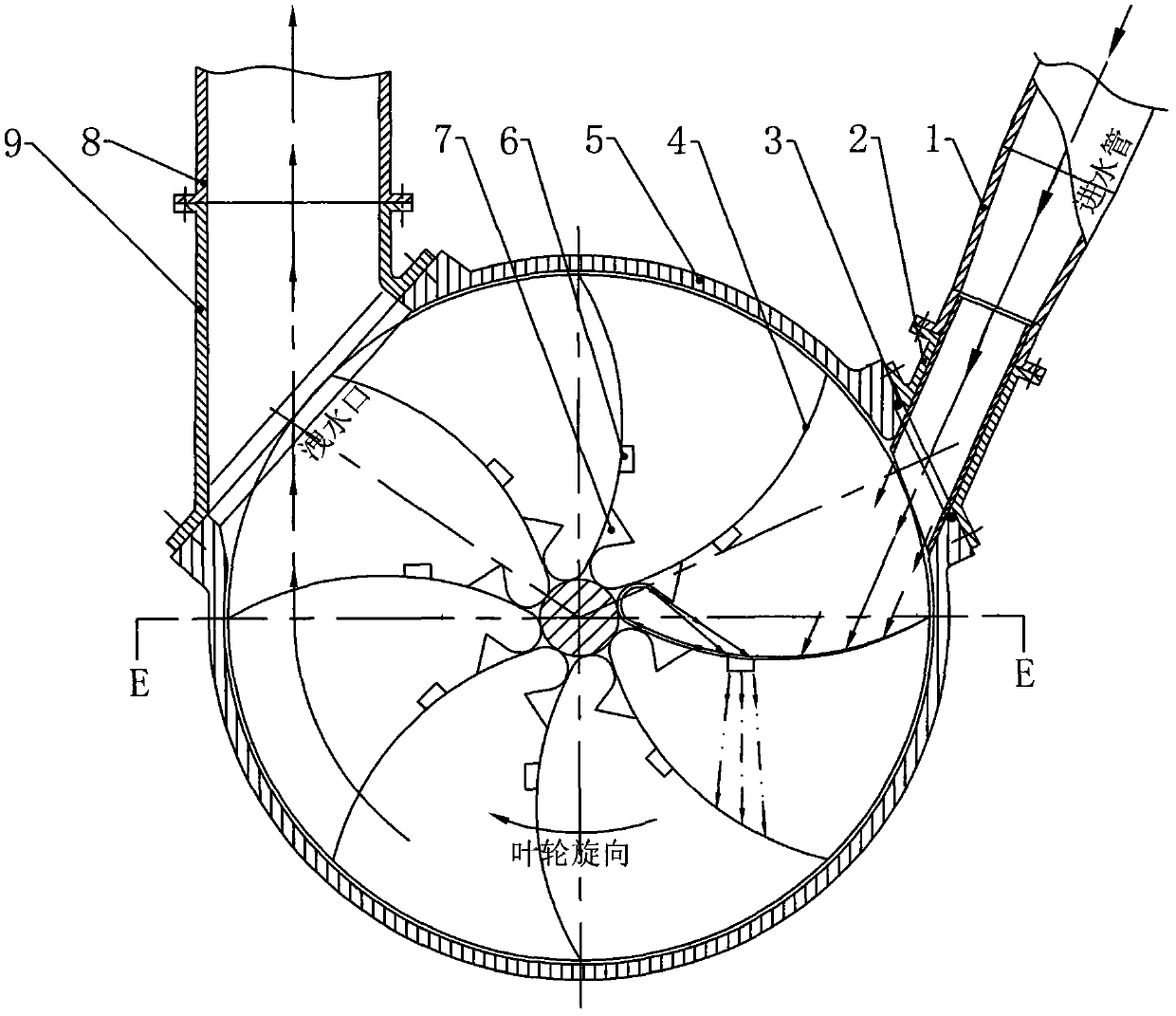
[0013] The power water source forms a columnar water flow from the water inlet pipe (1) through the water inlet interface seat (2) and enters the inner cavity of the turbine, and performs a first-stage jet impact on the boat-shaped blade (4) [as indicated by the arrow in the figure] to drive the impeller to rotate. When the power water source rushes along the front of the blade, it meets the preset secondary injection port (6) [that is, the split hole]. Part of the water flows into the split hole, and the other part of the water continues to rush forward and rushes into the bottom of the boat-shaped blade. The terminal, under the guidance of the deflector (7), flows back and is "introduced" into the split hole [that is, the second-level injection port (6)], and merges with the incoming water flow to form the second-level jet, which is aimed at the front-level blade The impact is carried out, and the continuous jet impact produced by the first-stage jet and the second-level jet ...


PUM


Abstract

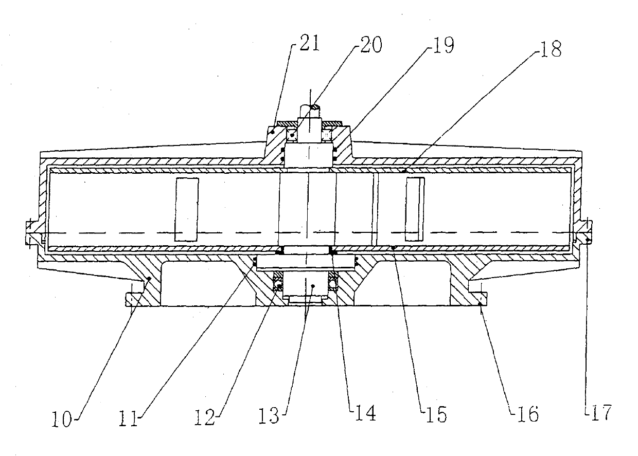
The invention discloses a secondary jet impulse water turbine. The water turbine is characterized in that an impeller is welded by a multilevel cymbiform blade and disc-shaped protecting sheets at two sides and a rotating wheel drawing group, and the rotating is internally connected with a combining cover type wheel shell through a ball bearing; the wheel shell is composed of a dish lower cover and a basin upper cover, the lower cover is utilized as a horizontal installed engine base for a water turbine and connected with a foundation bolt of reinforced concrete foundation in a fastening mode, thereby ensuring the operative stability of the water turbine; a two-stage continuous jet impactive manner is adopted for a power water source to drive the impeller to rotate to do work so as to drive a generator to operate to generate electricity; the power water source entering the water turbine pushes the impeller to rotate and processes along with the cymbiform blade and impeller, and enters into a drained area of the water turbine when the impeller rotates at 180-190 degrees; and dynamic water flow rushes and enters into a drain pipe of the water turbine along a discharge opening under the action of motion inertance and centrifugal force, and flows a water storage tank under the leading of the outer drain pipe for a water pump in the water storage tank to extract and then the extract water enters a water supply tower for reuse. The purpose of the water turbine provided by the invention is as follows: overcoming the defects of large vibration and the like of an existing spiral case type water turbine, and trying to excavate the work potential energy of the power water source further so as to reform the mode that the shaft flow type or mixed flow type is taken as a leading power water current to do work in the existing spiral water turbine.

Description

Technical field: [0001] The invention relates to a power device for driving a generating set to generate electricity in hydroelectric power generation equipment. Background technique: [0002] Since 2003, my country has introduced foreign pumped storage power generation technology and equipment to further broaden the application channels of hydropower generation. In the current pumped storage power generation mode, most of the turbines used are "volute" turbines, and axial flow or mixed flow hydraulic power is used to drive the operation of the turbine and the generating set to generate electricity. [0003] According to relevant data, the more prominent disadvantages of the volute turbine are: there is vibration during the operation of the turbine, and sometimes it is forced to stop due to resonance. The reason may be due to separate installation (the volute is embedded in the way) And the "pressure-holding" of the serpentine draft tube interferes with the movement rhythm ...

Claims


Application Information

Patent Timeline
IPC IPC(8): F03B1/04F03B11/02F03B13/00
CPCY02E10/226Y02E10/223Y02E10/20
Inventor 李光天李强
Owner 李光天
Learn More