Sealing valve

A technology of sealing valve and valve plate, applied in the field of sealing valve device, can solve the problems of equipment maintenance difficulty, hidden danger of equipment safety, deformation of driving arm, etc., and achieve the effects of simple and reasonable structure, good stress conditions, and reduced manufacturing difficulty

Active Publication Date: 2012-03-21
CISDI ENG CO LTD
View PDF4 Cites 4 Cited by
  • Summary
  • Abstract
  • Description
  • Claims
  • Application Information

AI Technical Summary

Problems solved by technology

In order to achieve the above two actions, the driving arm of the sealing valve is designed as a hollow shaft and a solid shaft in the form of unilateral coaxial transmission. The structure is complex, the processing is difficult, and the equipment maintenance is difficult.
At the same time, the driving arm of the valve plate is a cantilever beam structure. When the sealing valve is working, the driving arm bears a large load, which is easy to cause deformation or even breakage of the driving arm, which brings serious safety hazards to the equipment.

Method used


Image

  • Sealing valve
  • Sealing valve
  • Sealing valve

Examples


Embodiment 1

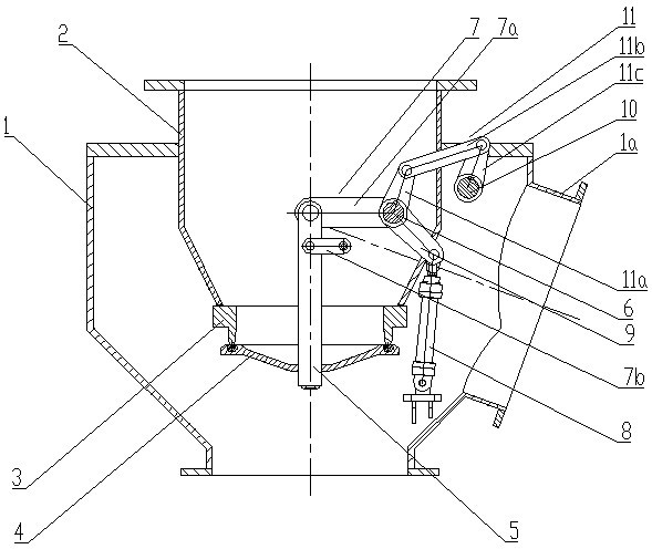
[0031] Such as Figure 1-Figure 5 As shown: the sealing valve of this embodiment includes a box body 1, a cylinder body 2 whose outlet end extends into the box body 1, a valve seat 3 fixedly arranged at the outlet of the cylinder body 2, and a cover for sealing on the valve seat 3 The functioning valve plate 4 and the valve plate opening and closing device for controlling the action of the valve plate 4, the valve plate opening and closing device includes a U-shaped transmission arm 5, which is coaxially and symmetrically arranged on both radial sides of the cylinder body 2 in a rotational fit manner Two valve plate drive shafts 6 on the box body 1, two drive cranks 7 symmetrically arranged on both radial sides of the cylinder body 2 and a driving device for driving the drive crank 7, the valve plate drive shaft 6 passes through the bearing The rotation fit is arranged on the box body 1, and the radial sides of the cylinder body 2 are preferably the two sides of the plane pass...

Embodiment 2

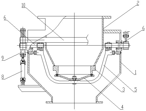
[0035] Such as Figure 6-Figure 8 As shown: the difference from Embodiment 1 is that one end of the driving crank 9 is hinged to the reciprocating output end of the hydraulic cylinder 8, and the other end is fixedly matched with the synchronous shaft 10 along the circumferential direction, so that the synchronous shaft 9 produces reciprocating rotation, driving two The valve plate driving half shaft 6 performs synchronous reciprocating rotation to realize the opening and closing of the valve plate 4 .

Embodiment 3

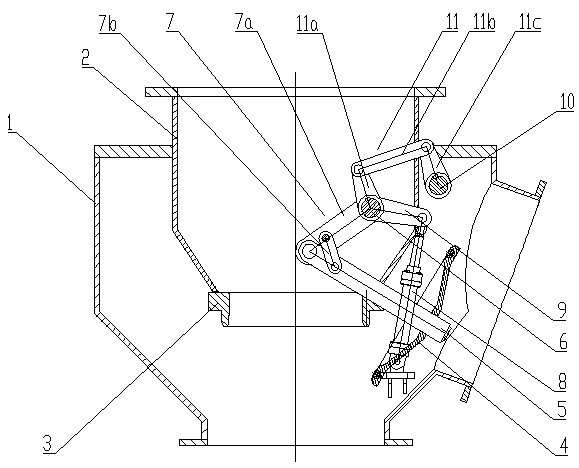
[0037] Such as Figure 9 , Figure 10 and Figure 11Shown: The difference from Embodiment 1 is that the synchronous device is removed in the structure of Embodiment 1, and two sets of driving devices are used to drive the two valve plate transmission half shafts 6 respectively, and the hydraulic cylinders 8 of the two driving devices are controlled to act synchronously , realize the synchronous reciprocating rotation of the two valve plate transmission half shafts 6, and realize the opening and closing of the valve plate 4.


PUM


Abstract

The invention discloses a sealing valve which comprises a box body, a cylinder body extending into the box body, a valve seat fixedly arranged at an outlet of the cylinder body, a valve plate covered on the valve seat to play a sealing role and a valve plate opening and closing device for controlling the valve plate to act. The invention has the beneficial effects that the valve plate opening andclosing device adopts a crank structure and is in transmission with a synchronizing device; the action of first translation and then turnover of the valve plate is realized, so that the device structure is effectively simplified, the movement space of the valve plate is reduced, and the power consumption is reduced; the two ends of a transmission arm with a U-shaped structure of the valve plate are respectively connected with a crank to form a simply-supported beam structure; compared with a transmission arm with a cantilever beam structure in the prior art, the transmission arm has better stress condition, better rigidity and intensity and is not easy to deform or break; meanwhile, each of transmission half shafts of the valve plate adopts a transmission structure of a bilateral solid shaft; and compared with a unilateral hollow shaft in the prior art, the solid shaft has a coaxial transmission structure, is simpler in structure and has low manufacturing and maintenance difficulty.

Description

technical field [0001] The invention relates to a sealing valve device, in particular to a sealing valve device matched with a material flow regulating valve in a shaft furnace charging system. Background technique [0002] When charging shaft furnaces, especially blast furnaces, the raw materials are generally loaded into the top cylinder first, and then the raw materials are loaded from the cylinder into the furnace through the material flow regulating valve. Due to the certain pressure in the furnace during the production process of the shaft furnace, in order to avoid the leakage of the gas in the furnace, a sealing valve is usually used to isolate the gas in the furnace from the outside world during the process of charging the cylinder. [0003] In the prior art, the valve plate of the top sealing valve of the shaft furnace generally has two actions of turning over and pressing when working, which are respectively driven by two oil cylinders. In order to achieve the ab...

Claims


Application Information

Patent Timeline
Patent Type & Authority Applications(China)
IPC IPC(8): F16K1/24F16K31/12F16K31/52
Inventor 郑军赵渭康马云峰王蜀生戴文军
Owner CISDI ENG CO LTD
Why Eureka
Try Eureka