Starting motor

A technology for starting motors and engines, which is applied in the direction of starting electric motors for engines, engine components, machines/engines, etc. It can solve problems such as low reliability, easy grease or dust, fast wear of motor gears and engine flywheels, and improve work efficiency. The effect of flexibility, convenient adjustment and simple structure

Inactive Publication Date: 2012-03-21
WOLONG ELECTRIC GRP CO LTD
View PDF6 Cites 2 Cited by
  • Summary
  • Abstract
  • Description
  • Claims
  • Application Information

AI Technical Summary

Problems solved by technology

There are four problems in this typical structure. Because the position of the motor gear and the engine flywheel is random, it often happens that the end face of the motor gear bears against the end face of the engine flywheel and cannot mesh normally. This is the most common and most common situation in the industry. Difficult to solve. Furthermore, even if the meshing is normal, the motor gear and the engine flywheel move at a high speed, causing the motor gear and the engine flywheel to wear quickly, with low reliability and easy failure. The contact surface of the rubber attached to the drive plate and the gear It is easy to enter grease or dust, causing the drive mechanism to slip or the torque is small, and the engine cannot be started. Finally, the high-speed motion between the motor gear and the engine flywheel causes a lot of noise

Method used


Image

  • Starting motor
  • Starting motor
  • Starting motor

Examples


Embodiment 1

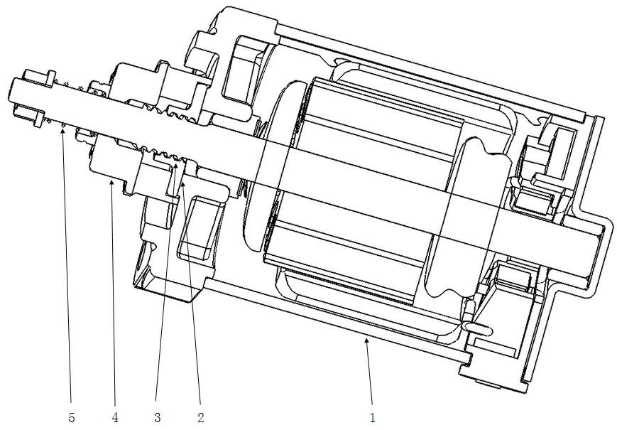
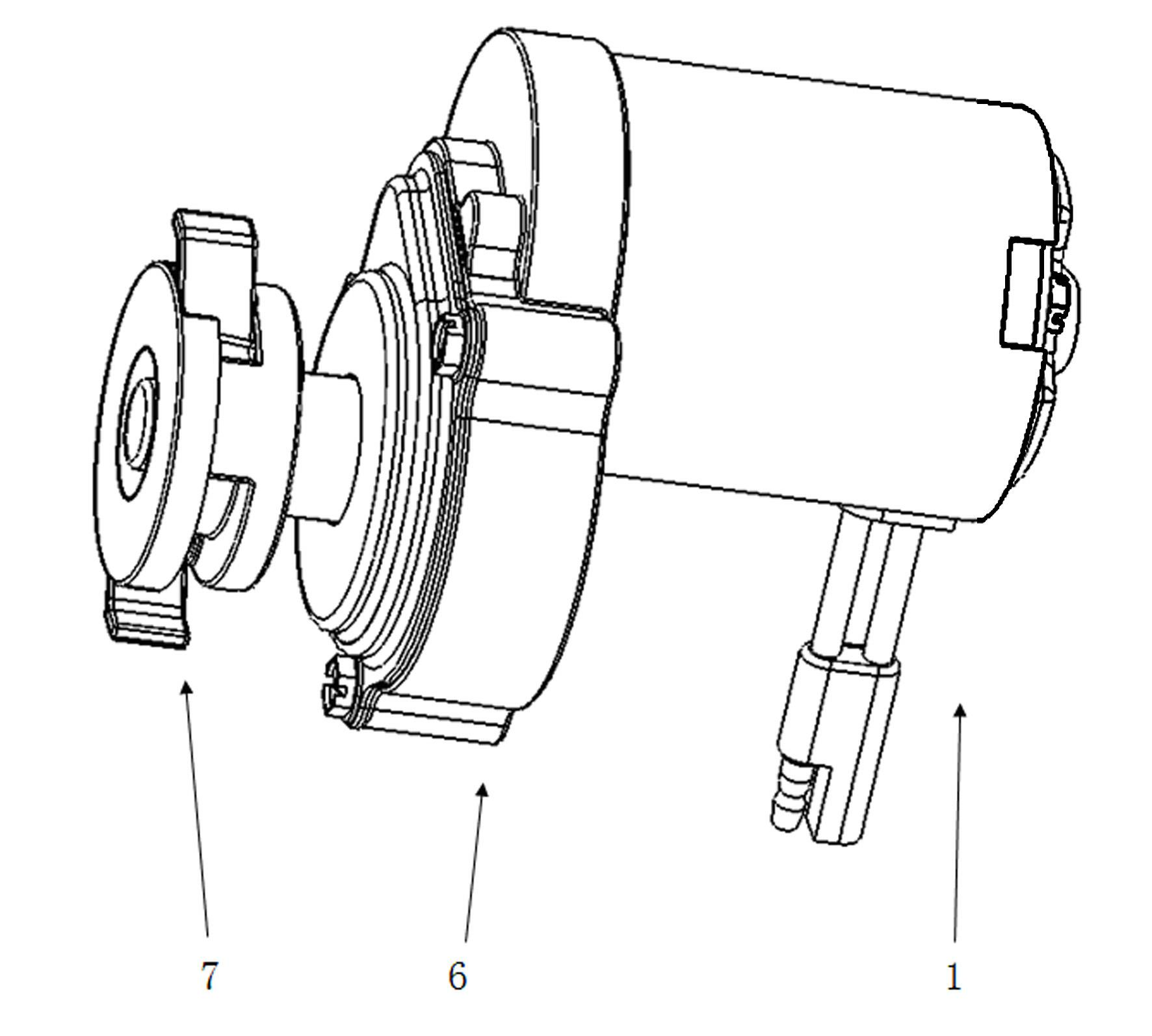
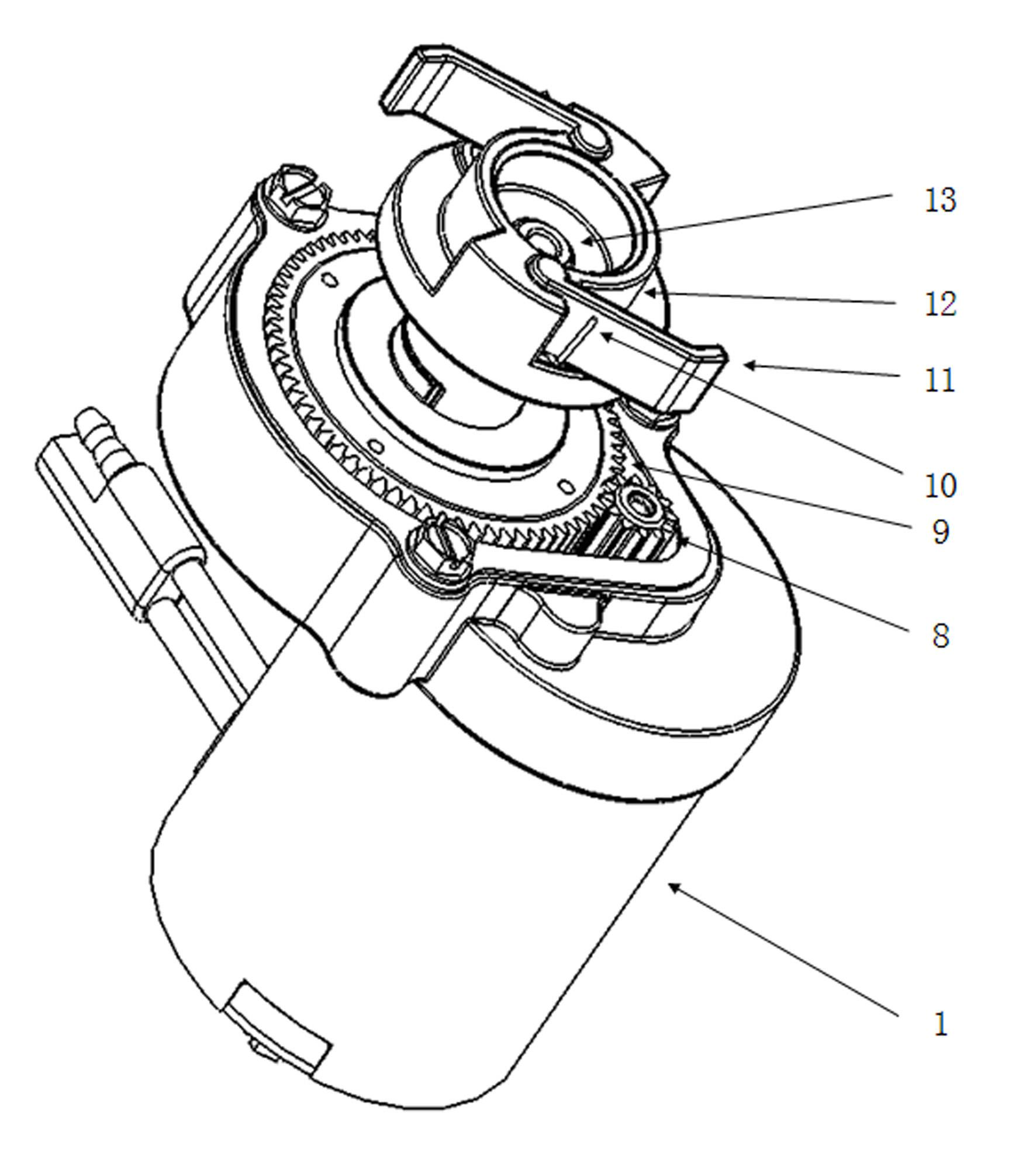
[0024] Embodiment one: if figure 2 , 3 , 5, the present invention includes a motor 1, a drive assembly 6 connected to the shaft of the motor 1, a torque converter 12 connected to the drive assembly 6 to follow its rotation, and at least one torque output piece connected to the torque converter 12 at one end 11. The expansion assembly 7 for opening the torque output sheet 11, the return spring 10 that is located between the torque converter 12 and the torque output sheet 11 to return the torque output sheet 11 and can collide with the torque output sheet 11 to The engine flywheel 17 that makes the torque output plate 11 drive its rotation, the engine flywheel 17 is provided with a thrust portion, and the torque output plate 11 changes the angle of rotation by opening the assembly 7 to increase the length of the overhanging torque converter 12 so that it is in contact with the engine flywheel 17. The pushing parts collide to drive the engine flywheel 17 to rotate. The drive a...

Embodiment 2

[0027] Embodiment 2: The difference from Embodiment 1 is that the bull gear 9 and the torque converter 12 are of an integrated structure, which is convenient for assembly.


PUM


Abstract

The invention provides a starting motor and relates to a motor. At present, an industry typical starting motor is worn quickly, has low reliability, is easy to be out of operation and can produce a big noise. The starting motor provided by the invention comprises a motor and is characterized by also comprising a driving assembly axially connected with the motor, a torque converter which is connected with the driving assembly to rotate along with the driving assembly, a torque output piece one end of which is connected to the torque converter, an unfolding assembly used for unfolding the torque output piece, a return spring which is arranged between the torque converter and the torque output piece and causes the torque output piece to reset and an engine flywheel which can collide with the torque output piece to cause the torque output piece to drive the engine flywheel to rotate, wherein the engine flywheel is provided with a pushed part, and the torque output piece changes a rotating angle and increases length extending outside the torque converter by virtue of the unfolding assembly, so that the torque output piece collides with the pushed part of the engine flywheel to drive the engine flywheel to rotate. According to the technical scheme adopted by, the structure is simple, the torque output piece can be meshed with the engine flywheel accurately and reliably, and noise during operation can be effectively reduced.

Description

technical field [0001] The invention relates to a starter motor. Background technique [0002] At present, typical starter motors in the industry (see attached figure 1 ) The structure is that the output end of the motor 1 has a gear 4 and the driving piece 2 through the spline 3. When the motor 1 starts, the moment of inertia is provided to the gear 4 and the driving piece 2, and the gear 4 and the driving piece 2 are ejected through the spline 3 and the engine flywheel Engaging, relying on the friction of the rubber attached to the drive plate 2 and the gear 4 to transmit torque, thereby starting the engine. After the engine starts, the motor is powered off, and the gear 4 and the drive plate 2 are pushed back to the original position by the reaction force of the spring 5 and the engine flywheel to the gear 4 and the drive plate 2, and the motor completes a cycle of work. There are four problems in this typical structure. Because the position of the motor gear and the en...

Claims


Application Information

Patent Timeline
Patent Type & Authority Applications(China)
IPC IPC(8): H02K7/00H02K7/116F02N11/00
Inventor 严伟灿周立新
Owner WOLONG ELECTRIC GRP CO LTD
Why Eureka
Try Eureka