
Amplifying Circuit

A technology of amplifying circuit and pre-amplifying circuit, which is applied in amplifiers, differential amplifiers, DC-coupled DC amplifiers, etc., and can solve the problems of differential amplifier circuits with limited work, constant current value, collector current can not fluctuate, etc.

Active Publication Date: 2012-03-21
ONKYO TECH KK
View PDF5 Cites 0 Cited by
  • Summary
  • Abstract
  • Description
  • Claims
  • Application Information

AI Technical Summary

Problems solved by technology

Therefore, the collector current of these transistors cannot fluctuate more drastically than said constant current in response to changes in the input signal
Unfortunately, the operation of conventional differential amplifier circuits is limited by the constant current value provided by the constant current source

Method used


Image

  • Amplifying Circuit
  • Amplifying Circuit
  • Amplifying Circuit

Examples


Embodiment Construction

[0045] Embodiments of the present invention will be described in detail below with reference to the accompanying drawings. The same or corresponding parts in the drawings are denoted by the same reference numerals, and description thereof will not be repeated.

[0046] Configuration of amplifier circuit 1

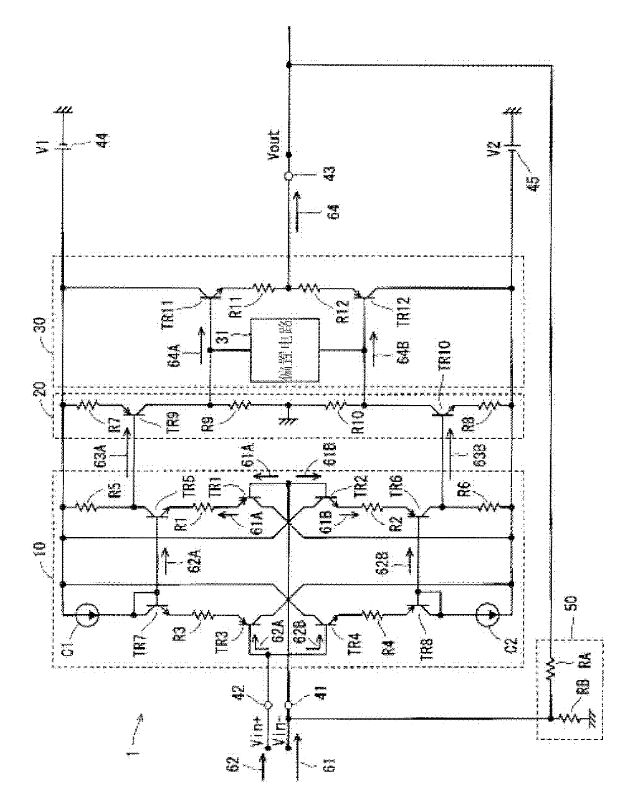
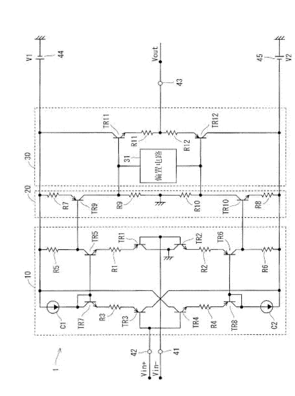
[0047] figure 1 is a circuit diagram illustrating the configuration of the amplifier circuit 1 according to this embodiment. refer to figure 1 The amplifying circuit 1 includes a preamplifying circuit 10 , a postamplifying circuit 20 , a buffer circuit 30 , an inverting input terminal 41 , a non-inverting input terminal 42 and an output terminal 43 . The feedback circuit 50 is isolated from the amplifier circuit 1 and connected to the outside of the amplifier circuit 1 .

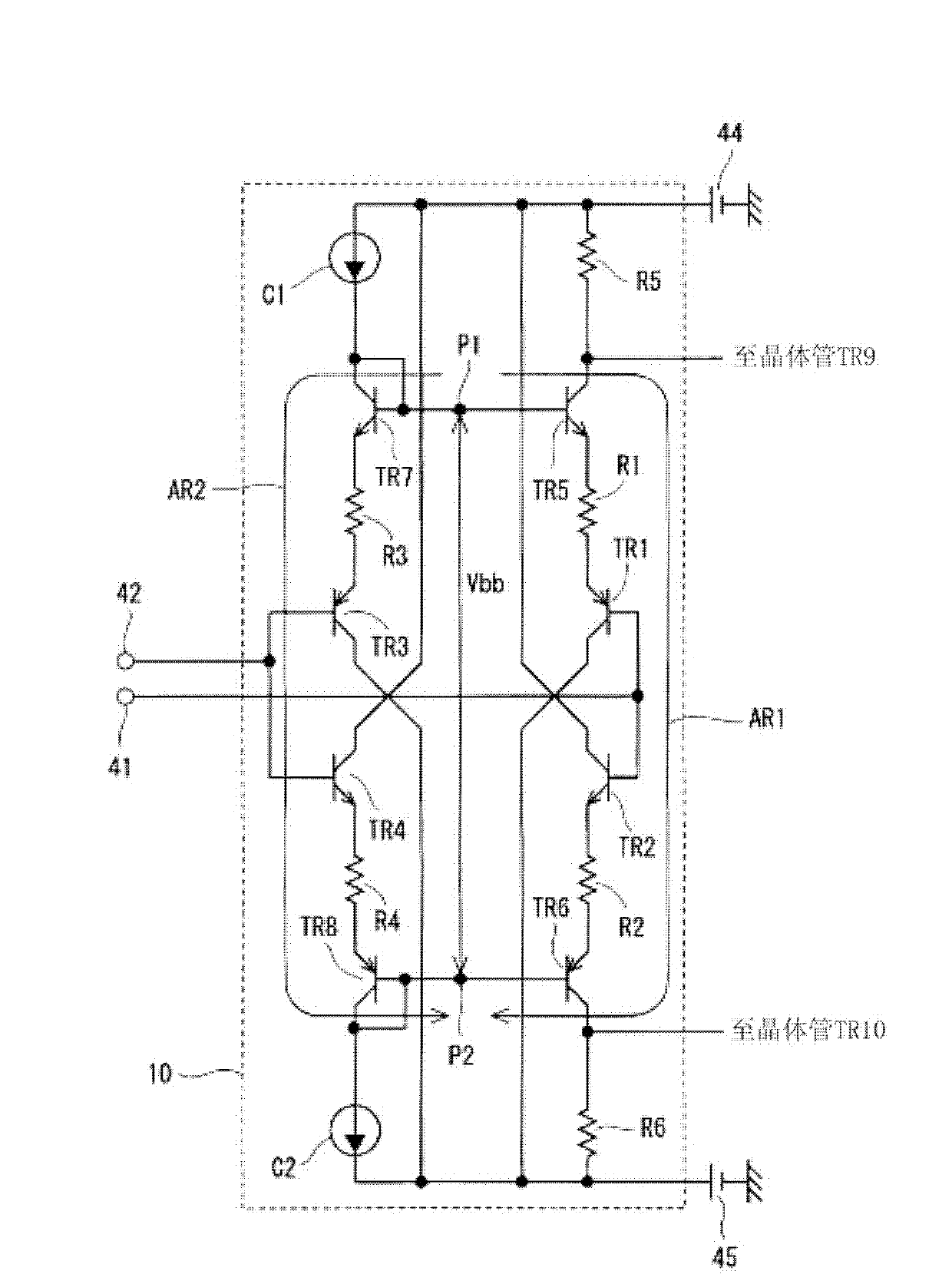
[0048] The pre-amplification circuit 10 amplifies the input signal 61 input to the inverting input terminal 41 and the input signal 62 input to the non-inverting input terminal 42, and outputs a pre-a...


PUM


Abstract

The first emitter follower circuit and the second emitter follower circuit can increase an input impedance on the side of the inverting input terminal in the amplifying circuit. As a result, when a feedback circuit is connected between the inverting input terminal and the output terminal of the amplifying circuit, a fluctuation in a gain of the amplifying circuit according to a configuration of the feedback circuit can be suppressed.

Description

technical field [0001] The present invention relates to amplifier circuits. Background technique [0002] When an operational amplifier is used, a negative feedback circuit for feeding back a part of the output signal with negative polarity is usually connected between the inverting input terminal and the output terminal. Therefore, the operable amplifier can be used as an inverting amplifying circuit or a non-inverting amplifying circuit. [0003] Japanese Patent Application Laid-Open No. 2010-35117 discloses a current feedback amplifier that amplifies an audio signal. The current feedback amplifier in Patent Document 1 has an AC feedback loop and a DC feedback loop independently as feedback circuits. The AC feedback loop feeds back a portion of the amplified audio signal in negative polarity. [0004] As a feature of such a current feedback amplifier, the input impedance of the current feedback amplifier is low from the viewpoint of the AC feedback loop. For this reaso...

Claims


Application Information

Patent Timeline
Patent Type & Authority Applications(China)
IPC IPC(8): H03F1/32H03F3/45H03F1/30
CPCH03F3/4517
Inventor 川口刚关谷守竹原优北川范匡
Owner ONKYO TECH KK
Features
  • Generate Ideas
  • Intellectual Property
  • Life Sciences
  • Materials
  • Tech Scout
  • Unparalleled Data Quality
  • Higher Quality Content
  • 60% Fewer Hallucinations
Learn More