Front bumper anti-collision beam and processing method thereof
A technology of a front bumper and a processing method, applied in the field of auto parts, can solve the problem of increasing the development cost of inspection tools, welding fixtures and welding tongs, energy consumption and management costs, troublesome welding and assembly processes, and difficult to guarantee the accuracy of parts, etc. problems, to achieve the effect of being beneficial to the body accuracy, structure and material selection optimization, and good part formability
- Summary
- Abstract
- Description
- Claims
- Application Information
AI Technical Summary
Problems solved by technology
Method used
Image

Examples
Embodiment 1
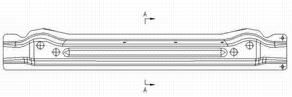
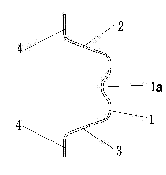
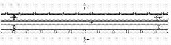
[0039] Such as figure 1 , figure 2 The shown front bumper anti-collision beam is composed of a load-bearing part 1, an upper support part 2 located at the upper end of the load-bearing part 1 and a lower support part 3 located at the lower end of the load-bearing part 1, and the three constitute the arch of the front bumper anti-collision beam shaped section. The bearing part 1 is a vertical plate, and the upper supporting part 2 and the lower supporting part 3 are both inclined plates, and both are symmetrically arranged on the upper and lower ends of the bearing part 1 . The middle part of the bearing part 1 is recessed inwardly to form a reinforcement part 1a. The reinforcement part 1a is preferably in the shape of a circular arc, which is convenient for stamping and forming, and can also be a square shape. The reinforcement part 1a provided on the bearing part 1 may be located at both ends of the bearing part 1, and the reinforcement part 1a on the bearing part 1 is no...
Embodiment 2
[0041] Such as image 3 , Figure 4 The shown front bumper anti-collision beam is composed of a load-bearing part 1, an upper support part 2 located at the upper end of the load-bearing part 1 and a lower support part 3 located at the lower end of the load-bearing part 1, and the three constitute the arch of the front bumper anti-collision beam shaped section. The bearing part 1 is a vertical plate, and the upper support part 2 and the lower support part 3 are both horizontal plates. The widths of the bearing part 1, the upper support part 2 and the lower support part 3 are equal (such as image 3 ), the length of the upper support part 2 is greater than the length of the lower support part 3 (such as Figure 4 ). The middle part of the carrying part 1 is recessed inwardly to form a reinforcing part 1a, and the reinforcing part 1a is square or arc-shaped. The reinforcement part 1a provided on the bearing part 1 may be located at both ends of the bearing part 1, and the re...
Embodiment 3
[0043] Such as Figure 5 , Figure 6 The shown front bumper anti-collision beam is composed of a bearing part 1 , an upper support part 2 located at the upper end of the bearing part 1 and a lower support part 3 located at the lower end of the bearing part 1 . The bearing part 1 is a stepped folded plate, and the stepped folded plate can be as Figure 6 Two steps as shown, three steps or more. Both the upper support part 2 and the lower support part 3 are horizontal plates. The anti-collision beam of the front bumper is integrally formed by hot stamping of a steel plate with a tensile strength of 400-600Mpa and a thickness of 1.8-2.5mm, and the tensile strength after hot stamping is 1300-1800Mpa.
PUM
| Property | Measurement | Unit |
|---|---|---|
| Tensile strength | aaaaa | aaaaa |
| Thickness | aaaaa | aaaaa |
| Tensile strength | aaaaa | aaaaa |
Abstract
Description
Claims
Application Information
 - R&D
- Intellectual Property
- Life Sciences
- Materials
- Tech Scout
- Unparalleled Data Quality
- Higher Quality Content
- 60% Fewer Hallucinations
Browse by: Latest US Patents, China's latest patents, Technical Efficacy Thesaurus, Application Domain, Technology Topic, Popular Technical Reports.
© 2025 PatSnap. All rights reserved.Legal|Privacy policy|Modern Slavery Act Transparency Statement|Sitemap|About US| Contact US: help@patsnap.com