Ampoule labeling and tray-loading machine

An ampoule and labeling technology, applied in the field of medical machinery, can solve the problems of efficiency discount, not easy to separate, and a large amount of labor, so as to achieve the effect of improving automation, reducing personnel, and improving efficiency

Inactive Publication Date: 2012-03-28
刘丙炎
View PDF4 Cites 4 Cited by
  • Summary
  • Abstract
  • Description
  • Claims
  • Application Information

AI Technical Summary

Problems solved by technology

[0002] At present, pharmaceutical machinery processing and manufacturing is a relatively precise processing technology. Injection trays are generally made of plastic materials, and in order to save materials, they are generally processed relatively thin. Because batches of medicine trays are relatively thin, they are easy to bond together, which is not easy. Separation must be separated by machine. Generally, manual separation is used. This method of separation is slow, requires a lot of labor, and the production efficiency is also very low.
In addition, after the medicine tray is separated, it is necessary to put medicine bottles inside, and the artificial tray must be filled after the tray is divided, so the work efficiency is greatly reduced, so the application number is 2011101311150, or the patent number is 2011201620287. The automatic palletizing machine described in the patent can automatically separate the pallets, which improves the work efficiency to a certain extent. In the later procedures, it takes a lot of manpower and material resources to print, label, and pack the ampoules. Although the all-in-one machine described in the patent No. 2011201587429 and the name "Separate Printing Linkage Machine" is adopted, there are also many shortcomings, such as the transmission of the medicine tray needs to consume a lot of electric energy, and sometimes the ampoule cannot be accurately printed. put into the medicine tray, thus reducing the work efficiency

Method used


Image

  • Ampoule labeling and tray-loading machine
  • Ampoule labeling and tray-loading machine
  • Ampoule labeling and tray-loading machine

Examples


Embodiment Construction

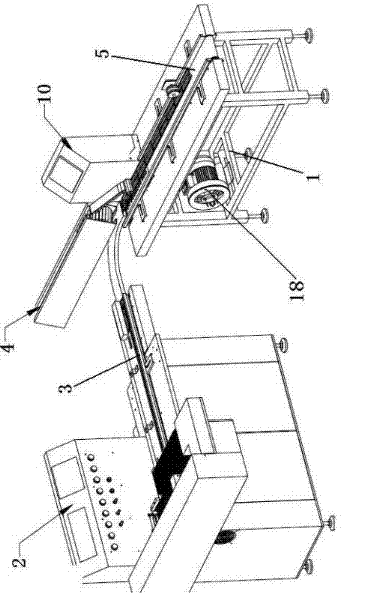
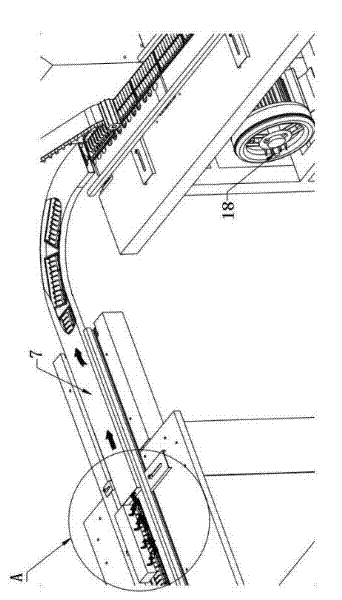
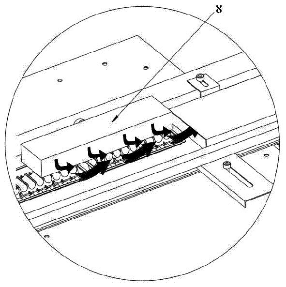
[0017] As shown in 1, 2, and 3, the present invention includes a frame 1, a drug tray feeding conveyor belt 3 arranged on the frame 1 and docked with the sub-tray machine 2, and a conveyor belt 4 provided on the frame 1 with an ampoule conveyor belt 4. The labeling machine, the medicine tray discharge conveyor belt 5 docked with the ampoule conveyor belt 4, the air pump 18 and the motor 6 arranged on the frame 1, and the wind tunnel 7 is docked at the end of the medicine tray feed conveyor belt 3, and the air The entrance of the tunnel 7 is provided with an air outlet pipe 8 communicating with the air pump 18, and an adsorption conveying mechanism is connected to the outlet of the wind tunnel 7. The side frame 1 is provided with a wallboard 10, and the ampoule conveyor belt 4 is arranged on the wallboard 10 above the adsorption conveying mechanism.

[0018] Such as Figure 5 As shown, the adsorption conveying mechanism includes an adsorption conveyor belt 11, an adsorptio...


PUM


Abstract

The invention belongs to the field of medicine machinery and specifically relates to an ampoule labeling and tray-loading machine. The ampoule labeling and tray-loading machine comprises a frame, a medicine tray feeding conveyor belt which is arranged on the frame and in butt joint with a tray separating machine, a labeling machine which is arranged on the frame and comprises an ampoule conveyor belt, a medicine tray discharging conveyor belt which is in butt joint with the ampoule conveyor belt, an air pump arranged on the frame and a motor, wherein an air hole is in butt joint with the tail end of the medicine tray feeding conveyor belt, an air outlet pipe communicated with the air pump is arranged at an inlet of the air hole, an adsorption type conveying mechanism is in butt joint with an outlet of the air hole, the adsorption type conveying mechanism is in butt joint with the medicine tray discharging conveyor belt, a wall panel is arranged on the frame which is arranged on one side of the adsorption type conveying mechanism, and the ampoule conveyor belt is arranged on the wall panel above the adsorption type conveying mechanism. The ampoule labeling and tray-loading machine has the advantages of being accurate in tray loading, reducing the cost and improving the efficiency.

Description

technical field [0001] The invention belongs to the field of medical machinery, in particular to an ampoule labeling machine. Background technique [0002] At present, pharmaceutical machinery processing and manufacturing is a relatively precise processing technology. Injection trays are generally made of plastic materials, and in order to save materials, they are generally processed relatively thin. Because batches of medicine trays are relatively thin, they are easy to bond together, which is not easy. Separation must be separated by machine, and manual separation is generally used. This method of separation is slow, requires a lot of labor, and the production efficiency is also very low. In addition, after the medicine tray is separated, it is necessary to put medicine bottles inside, and the artificial tray must be filled after the tray is divided, so the work efficiency is greatly reduced, so the application number is 2011101311150, or the patent number is 2011201620287...

Claims


Application Information

Patent Timeline
Patent Type & Authority Applications(China)
IPC IPC(8): B65B43/00
Inventor 刘丙炎
Owner 刘丙炎
Why Eureka
Try Eureka