Directional cracking device for coal mines

A directional fracturing and coal mine technology, applied in the fields of mining fluids, wellbore/well components, earth-moving drilling, etc., can solve the problems of water gun detachment, drilling destruction, drilling, etc., to achieve easy production and processing, and improve work efficiency , the effect of improving work efficiency

Inactive Publication Date: 2012-03-28
安阳鑫龙煤业(集团)有限责任公司
View PDF6 Cites 5 Cited by
  • Summary
  • Abstract
  • Description
  • Claims
  • Application Information

AI Technical Summary

Problems solved by technology

There are many disadvantages in this method. First, the sealing problem after the high-pressure water gun is inserted into the drill hole cannot be solved well. It needs very tedious fixing work to firmly seal and fix the high-pressure water gun on the orifice. There are still two common problems in this way. One is that it takes a long time to seal and fix, which affects the mining progress, and the other is that th

Method used


Image

  • Directional cracking device for coal mines
  • Directional cracking device for coal mines
  • Directional cracking device for coal mines

Examples


Embodiment 1

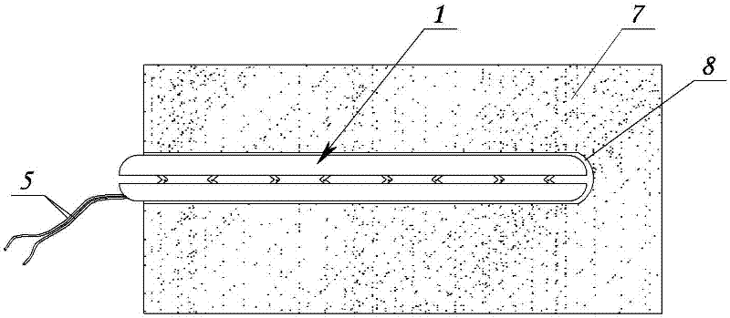
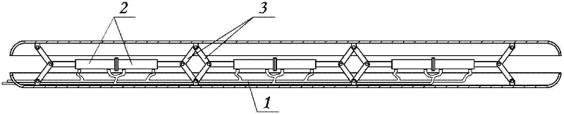
[0016] Embodiment one: see figure 1 , figure 2 The directional fracturing device 1 for coal mines comprises two interlocking strip arcuate support base plates 1a and 1b, at least a pair of lying hydraulic cylinders 2 are arranged between the two support base plates, and the paired two hydraulic cylinders The root of each hydraulic cylinder is butted, and the end of the piston rod of each hydraulic cylinder is symmetrically hinged with a push rod 3, and the inner surface of the strip-shaped arc-shaped support plate is provided with a hinge ear 4, and each push rod 3 is hinged on the corresponding hinge ear 4 through a pin shaft. . The oil inlet pipe of each hydraulic cylinder is connected with the total oil inlet pipe, and the oil outlet pipe of each hydraulic cylinder is connected with the total oil outlet pipe.

Embodiment 2

[0017] Embodiment two: see figure 1 and image 3 , the content is basically the same as that of Embodiment 1, and the similarities will not be repeated. The difference is that there are many pairs of horizontal hydraulic cylinders 2, and the push rods 3 of adjacent hydraulic cylinders are jointly hinged on the same hinge ear 4, which can improve the middle part. top force.

Embodiment 3

[0018] Embodiment three: see figure 1 and Figure 4 , The content is basically the same as that of Embodiment 1, and the similarities will not be repeated. The difference is that each hinge ear is evenly distributed and the inner sidewall of the strip-shaped arcuate support base plate, and the paired horizontal hydraulic cylinders 2 are distributed at intervals.


PUM


Abstract

The invention relates to a directional cracking device for coal mines, which comprises two strip-shaped cambered bottom supporting plates fastened with each other oppositely, at least one pair of horizontal hydraulic cylinders are arranged between the two bottom supporting plates, the roots of the pair of hydraulic cylinders are connected, push rods are symmetrically articulated with the tail end of the piston rod of each hydraulic cylinder, the other ends of the push rods are respectively articulated with the inner surfaces of the strip-shaped cambered bottom supporting plates, an oil inlet tube of each hydraulic cylinder is communicated with an oil inlet main, and an oil outlet tube of each hydraulic cylinder is communicated with an oil outlet main. By utilizing a plurality of small hydraulic cylinders as pushing power, the directional cracking device applies expanding pressure on the sidewall of a coal bed borehole by means of the bottom plate on one end of each hydraulic cylinder and the pushing plate or top plate on the other end of each hydraulic cylinder, so that cracks can be produced in the bore hole to facilitate further mining. The directional cracking device is highly convenient to operate, and greatly increases the working efficiency and the mining efficiency. The directional cracking device is safe and reliable, and cannot pollute and destroy the working environment.

Description

technical field [0001] The invention relates to an auxiliary tool for coal mine development, in particular to a directional fracturing device for coal mines. Background technique [0002] In the current coal mining process, it is necessary to drill holes in the coal seam with a drilling tool, then use a high-pressure water gun to draw water into the hole, and use the pressure of the high-pressure water gun to crack the hole wall in the drill hole for further mining. There are many disadvantages in this method. First, the sealing problem after the high-pressure water gun is inserted into the drill hole cannot be solved well. It takes very tedious fixing work to securely seal the high-pressure water gun to the orifice. There are still two common problems in this way. One is that it takes a long time to seal and fix, which affects the mining progress, and the other is that the sealed and fixed structure is still not firm, and the water gun often breaks away after the water pres...

Claims


Application Information

Patent Timeline
IPC IPC(8): E21B43/267
Inventor 秦保常李东东秦翠芳冯文亮赵亮
Owner 安阳鑫龙煤业(集团)有限责任公司
Why Eureka
Try Eureka