Variable area type differential pressure flowmeter adopting variable area type differential pressure flow structure

A differential pressure flowmeter and variable area technology, applied in the field of variable area differential pressure flow structure and variable area differential pressure flowmeter, can solve the problems of not being completely solved, large permanent pressure loss, etc., to improve the range ratio High, easy to install, high precision effect

Inactive Publication Date: 2012-03-28
重庆威巴仪器有限责任公司
4 Cites 4 Cited by

AI-Extracted Technical Summary

Problems solved by technology

Therefore, generally speaking, the turndown ratio of the orifice flowmeter is limited to about 4:1.
And t...

Abstract

The invention discloses a variable area type differential pressure flowmeter adopting a variable area type differential pressure flow structure. The flow structure comprises a fixed sleeve, a channel which is used for connecting a fluid pipeline is arranged in the middle of the fixed sleeve, at least one blade of positioning wheel plate is stretched from an inner wall of the middle of the channelfrom the top down, a threaded rod coaxial with the channel is fixed on a hanging end of the positioning wheel plate, a throttling slip mass which slidably matched with the threaded rod in an coaxial manner is sheathed in the middle of the threaded rod, a compression spring is sheathed on the threaded rod between a rear end of the throttling slip mass and a limit step, the throttling slip mass comprises a section of a spindle structure, and a pressure tapping holeI and a pressure tapping holeII are respectively arranged on the fixed sleeve. Due to the adoption of the flowmeter, therefore, limitation that a traditional differential pressure type flowmeter has a fixedly invariant throttling area ratio and an invariant measurement range can be broken down, during measurement process, throttling area can be changed along with flow change, a meter signal (differential pressure) is in linear relationship with flow, measuring range altitude intercept can be greatly improved, and measurement requirements for different flow ranges can be met.

Application Domain

Volume/mass flow by differential pressure

Technology Topic

Linear relationshipEngineering +5

Image

  • Variable area type differential pressure flowmeter adopting variable area type differential pressure flow structure
  • Variable area type differential pressure flowmeter adopting variable area type differential pressure flow structure
  • Variable area type differential pressure flowmeter adopting variable area type differential pressure flow structure

Examples

  • Experimental program(1)

Example Embodiment

[0028] The preferred embodiments of the present invention will be described in detail below with reference to the accompanying drawings. It should be understood that the preferred embodiments are only for illustrating the present invention, not for limiting the protection scope of the present invention.
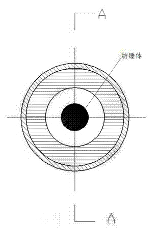
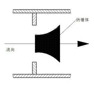
[0029] The research of the present invention is based on the following theories: figure 1 with figure 2 As shown, when the fluid flows through the throttle, a pressure difference between front and rear is formed. The differential pressure causes the spindle to move, and the moving distance is , The outer contour aperture of the spindle is. Under the action of the spring’s restoring force, the spindle moves a certain distance and then stands still, reaching a state of equilibrium, and the differential pressure Is equal to the stubborn coefficient of the spring And itinerary The product of, namely:
[0030] —— ( = Spring recovery coefficient)
[0031] We know that the volume flow Equal to flow rate Multiply the circulation area , Then:
[0032] ——
[0033] According to Bernoulli equation, the flow velocity And differential pressure Is proportional to the square root of, then:
[0034] ---—— ( = Constant)
[0035] By formula Learned:
[0036] ——
[0037] The outer contour aperture of the unique spindle is Design so that the circulation area versus When linear, there are:
[0038] —— ( = Constant)
[0039] By formula Learned:
[0040] —— ( = Constant)
[0041] By formula Learned And displacement Linear, and by the formula Know the differential pressure And displacement Linearity, in summary versus Linear, namely:
[0042] ( = Constant)
[0043] Thereby greatly expanding the equipment range ratio.
[0044] According to the above principles, such as image 3 As shown, the variable area differential pressure flow structure of the present invention includes a fixed sleeve 1. A channel 2 for connecting a fluid pipeline is opened at the center of the fixed sleeve 1. The longitudinal section of the channel 2 is trapezoidal, with the large end of the trapezoid and The small ends are respectively the fluid inlet end and the fluid outlet end. The inner wall of the middle of the channel extends from top to bottom with positioning wheel plates 3. In this embodiment, the number of positioning wheel plates is 3 and they are evenly arranged along the inner wall of the middle of the channel. , The positioning wheel plates are perpendicular to the inner wall, and the angle between the suspended ends of adjacent positioning wheel plates is 60°.
[0045] The hanging end of the positioning wheel plate 3 is concentratedly fixed with a screw 4 coaxial with the channel. The front end of the screw 4 is fixed with the positioning wheel plate 3, the rear end of the screw 4 is provided with a limit step 5, and the middle of the screw 4 is provided with A throttling slide body 6 slidingly fitted with the screw in a coaxial manner. A compression spring 7 is sleeved on the screw between the rear end of the throttling slide body 6 and the limit step 5. The throttling slide body 6 includes a section concentric with the screw The spindle structure 8, the small end of the spindle structure 8 faces the fluid inlet end of the channel, under normal conditions, the throttling sliding body 6 is under the action of the compression spring, the large end edge of the spindle structure 8 In close contact with the inner wall of the channel and divide the channel into a front cavity and a back cavity, the front cavity includes the fluid inlet end of the channel, and the back cavity includes the fluid output end of the channel;
[0046] The fixing sleeve 1 is also provided with a pressure hole I 9 and a pressure hole II 10 respectively. The pressure hole I is used to connect the front cavity and the external pressure measuring device, and the pressure hole II is used to connect the rear cavity and the external measuring device. 压装置。 Pressure device.
[0047] As a further improvement, the length of the spindle structure accounts for 1/2 to 2/3 of the total length of the throttle sliding body.
[0048] As a further improvement, the compression spring is made of INCONEL X750 special alloy, and it has been hardened for several hours at a high temperature of 650℃ and a high temperature heat treatment of 400℃ or more, which has good elasticity and anti-relaxation, suitable for long-term use .
[0049] Such as Figure 4 As shown, the variable area differential pressure flowmeter of the present invention includes the variable area differential pressure flow structure 15 as described above, and also includes a clamping flange I 11 and a clamping flange II 12 made of stainless steel, The clamping flange I and the clamping flange II adopt the clamp structure to tightly clamp the variable area differential pressure flow structure between the two. The middle part of the clamping flange I and the clamping flange II is provided for The pipe hole of the docking channel. Through the adoption of a wafer-type structure, it is convenient for the owner to install and debug, and also reduces the owner's use cost.
[0050] In order to achieve good sealing performance, a sealing ring 13 is provided on the joint surface of the flange and the fixing sleeve. The bolt structure 14 is used for firm connection between the flange and the flange.
[0051] The invention adopts a flowmeter with a variable area differential pressure flow structure, which breaks the limitations of the traditional differential pressure flowmeter that its throttling area ratio is constant and the measurement range is unchanged. During the measurement process, the throttling area increases with the flow rate. Change and change, the instrument signal (differential pressure) has a linear relationship with the flow, which greatly improves the range ratio (up to 100:1), and meets the measurement requirements of different flow ranges.
[0052] Finally, it should be noted that the above embodiments are only used to illustrate the technical solutions of the present invention and not to limit them. Although the present invention has been described in detail with reference to the preferred embodiments, those of ordinary skill in the art should understand that the technical solutions of the present invention can be implemented Modifications or equivalent replacements without departing from the purpose and scope of the technical solution shall be covered by the scope of the claims of the present invention.

PUM

no PUM

Description & Claims & Application Information

We can also present the details of the Description, Claims and Application information to help users get a comprehensive understanding of the technical details of the patent, such as background art, summary of invention, brief description of drawings, description of embodiments, and other original content. On the other hand, users can also determine the specific scope of protection of the technology through the list of claims; as well as understand the changes in the life cycle of the technology with the presentation of the patent timeline. Login to view more.

Similar technology patents

Gas flowmeter

PendingCN107796452AIncrease the turndown ratio
Owner:矽翔微机电系统(上海)有限公司

Flux integrating instrument of iterating differential pressure

InactiveCN1661337AIncrease the turndown ratiolow cost
Owner:张国仁

Classification and recommendation of technical efficacy words

  • Increase the turndown ratio

Flux integrating instrument of iterating differential pressure

InactiveCN1661337AIncrease the turndown ratiolow cost
Owner:张国仁

Gas flowmeter

PendingCN107796452AIncrease the turndown ratio
Owner:矽翔微机电系统(上海)有限公司
Why Eureka
Try Eureka