High voltage isolation switch

A high-voltage isolation switch, knife switch technology, applied in the direction of air switch parts, contact meshing, contact electrical connection, etc., can solve the problems of electrical conductivity, safety and reliability are not ideal, environmental adaptability and withstand voltage level It is not very high, the conduction effect of the high-voltage isolation switch is not very ideal, etc., to improve the anti-ultraviolet ability, improve the environmental adaptability and withstand voltage level, and avoid poor circuit conduction.

Inactive Publication Date: 2012-03-28
王漳泉 +2
View PDF4 Cites 21 Cited by
  • Summary
  • Abstract
  • Description
  • Claims
  • Application Information

AI Technical Summary

Problems solved by technology

In addition to the complicated installation and high cost of such a structure, the circuit resistance of the entire switch is relatively large during the working process, resulting in unsatisfactory conductivity, safety and reliability;
[0007] 4. The knife switch is hinged to the screw on the static contact. The two ends of the screw are covered with ordinary springs to press against the knife switch. Because the ordinary spring needs to provide a relatively large pressure within a large stroke, and the contact area is small , so that the conduction effect of the high-voltage isolation switch is not very ideal, and the economy and safety are average;
[0008] 5. There are umbrella groups with the same diameter on the outer circumference of the insulating support of the existing isolating switch, and the environmental adaptability and withstand voltage level of the product are not very high.

Method used


Image

  • High voltage isolation switch
  • High voltage isolation switch
  • High voltage isolation switch

Examples


Embodiment Construction

[0028] The present invention will be further described in conjunction with the accompanying drawings and specific embodiments.

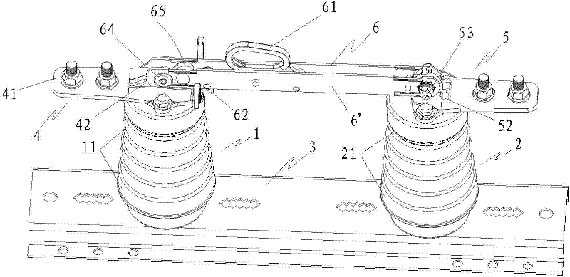
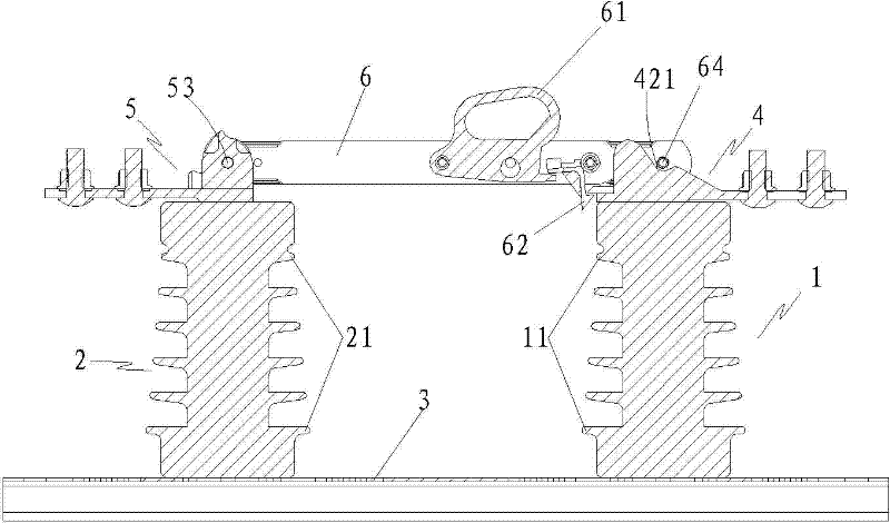
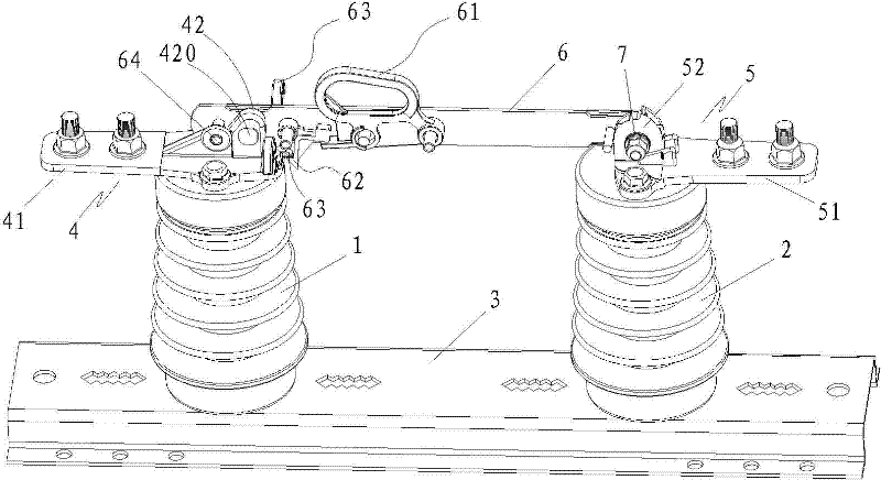
[0029] Examples such as Figures 1 to 4 Shown: a high-voltage isolating switch, including: a first insulating support 1 and a second insulating support 2 vertically fixed on a mounting plate 3, and a moving contact 4 and a static contact 5 are respectively fixed on the two insulating supports, and the static contact A knife switch is hinged on the head 5, and the other end of the knife switch is lapped on the moving contact 4, wherein the moving contact 4 and the static contact 5 are integrally formed with the corresponding terminal, and one end of the knife switch is the contact portion , the other end is the wiring part, that is, the moving contact part 42 and the first connecting terminal 41 are integrally formed, and the static contact part 52 and the second connecting terminal 51 are integrally formed. The knife switch includes a first knife sw...


PUM


Abstract

The invention provides a high voltage isolation switch which comprises two insulation pillars which are vertically fixed on an installation plate. The two insulation pillars are fixed with a moving contact and a static contact respectively, the static contact is hinged with an isolator, and another end of the isolator is in overlapping joint with the moving contact, wherein the moving contact and a corresponding binding post are one-piece shaping, the static contact and a corresponding binding post are one-piece shaping, contact between the isolator and the moving contact is a surface to surface contact mode, and conductive connection is realized to reduce loop resistance of the whole isolation switch. Peripheral of the insulation pillar is provided with a parachute cluster which enlarges gradually from one end to another end of the insulation pillar, a screw is pivoted on the static contact, and the screw is sleeved with a disk spring set which presses against the isolator. Since employing the above structure, conduction performance of the high voltage isolation switch is improved, whole loop resistance is substantially reduced to 45-50 micro Omegas, and security and reliability in working are improved.

Description

technical field [0001] The invention discloses a high-voltage isolating switch, belongs to the technical field of isolating switch manufacturing according to the International Patent Classification (IPC), and in particular relates to a high-voltage isolating switch with lower loop resistance. Background technique [0002] The high-voltage isolating switch is mainly used in the outdoor AC 10-40.5kv, 50HZ power system to switch the load live high-voltage line and isolate the live high-voltage line from the high-voltage busbar or circuit breaker and other electrical equipment to be repaired. The product is widely applicable Electric power, railway, mine, oil field and other fields. [0003] The existing high-voltage isolating switch includes: two insulating pillars vertically fixed on the mounting plate, there are umbrella groups with the same diameter on the insulating pillars, moving and static contacts are respectively fixed on the insulating pillars, and the two insulating ...

Claims


Application Information

Patent Timeline
Patent Type & Authority Applications(China)
IPC IPC(8): H01H31/02H01H1/58H01H1/12
Inventor 王漳泉吴承德郭文川
Owner 王漳泉
Why Eureka
Try Eureka