Floating platform for extracting wind energy

A floating platform and wind energy technology, which is applied in wind power generation, wind engines, floating buildings, etc., can solve problems such as the inability to install wind farms economically, and achieve the effect of increasing the restoring torque

Inactive Publication Date: 2012-03-28
APIA XXI SA
View PDF10 Cites 4 Cited by
  • Summary
  • Abstract
  • Description
  • Claims
  • Application Information

AI Technical Summary

Problems solved by technology

The invention solves the problems that arise at sea at depths greater than 50m where it is not possible to install wind farms economically

Method used


Image

  • Floating platform for extracting wind energy
  • Floating platform for extracting wind energy

Examples


Embodiment Construction

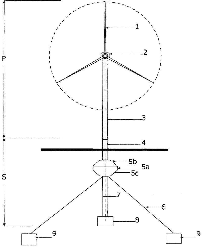
[0021] if available in figure 1 As seen in , the proposed floating platform for harvesting wind energy here comprises: a superstructure (4) linking a wind turbine tower (3) to a buoyancy tank (5). The superstructure (4) is made of steel and connected to the wind turbine tower (3) and buoyancy tanks (5) by bolted flanges. Its purpose is to ensure that the wind turbine tower (3) is always above the water surface and the pontoon (5) is always submerged.

[0022] The drag exerted by the flow on the structure depends on the size of the flow and the cross-sectional area exposed to the flow. On the other hand, the structure is affected by the action of waves, which also exert drag forces and cause the system to make oscillatory motions. These forces are large at the surface, decrease with depth, and are almost zero on the seabed. In order to reduce the action of water currents and waves on the structure, it is proposed that the upper part (4) acts as a gas-moisture interface and h...


PUM


Abstract

The invention relates to a floating platform for extracting wind energy, comprising a structure (S) for supporting the installation (P) formed by a wind turbine tower (3), a nacelle (2) and the corresponding blades (1) thereof. The supporting structure (S) consists of an upper structure (4) that joins the installation (P) to the floating tank (5) that is, in turn, connected to the ballast tank (8) by means of a lower structure (7), said ballast tank (8) being designed to control the centre of gravity of the installation and to adjust the floating line by means of mass distribution.

Description

technical field [0001] The main object of the invention relates to floating platforms for wind power generation. Such a floating platform can be applied in the field of renewable energies, in particular in the area of ​​so-called offshore wind energy, ie at sea and away from the coast. Background technique [0002] Offshore wind energy projects have higher installation, operation and maintenance costs than those onshore. Foundations for offshore wind turbine towers represent a major part of the initial cost which increases with depth, so at depths of 50 meters or more it is currently economical to employ floating platforms. [0003] Finding suitable sites for installing on-shore wind turbines is becoming increasingly difficult. Therefore, the international trend is to install offshore wind farms in the territorial waters of various countries. In many places, however, the water reaches a depth of 50 meters a few kilometers from shore. Therefore, in order to install a larg...

Claims


Application Information

Patent Timeline
Patent Type & Authority Applications(China)
IPC IPC(8): F03D11/04
CPCF05B2240/97Y02E10/727Y02E10/728B63B35/44F03D11/04B63B2035/446F03D13/25Y02E10/72F03D13/20
Inventor 马科斯·J·潘塔莱翁普列托奥斯卡·拉蒙·拉莫斯古铁雷斯米格尔·安格尔·古铁雷斯马丁内斯
Owner APIA XXI SA
Why Eureka
Try Eureka