Spectral imaging

A spectrum and imaging system technology, applied in the field of spectral imaging

Active Publication Date: 2012-03-28
KONINKLIJKE PHILIPS ELECTRONICS NV
View PDF7 Cites 8 Cited by
  • Summary
  • Abstract
  • Description
  • Claims
  • Application Information

AI Technical Summary

Problems solved by technology

However, there is an unresolved need in other techniques for modulating the spectral information in the detector signal

Method used


Image

  • Spectral imaging
  • Spectral imaging
  • Spectral imaging

Examples


Embodiment Construction

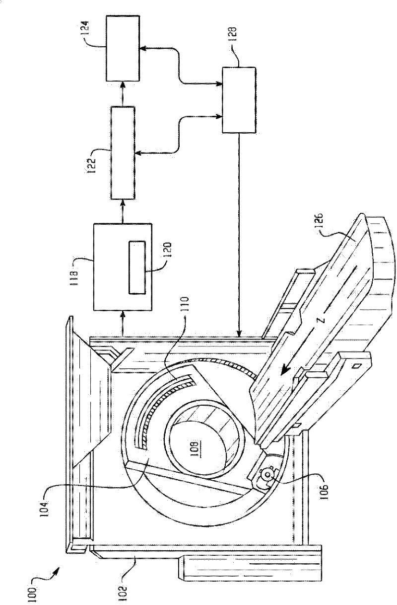
[0015] figure 1 An imaging system 100 such as a computed tomography (CT) scanner is shown. System 100 includes a generally stationary gantry 102 and a rotating gantry 104 . The rotating gantry 104 is rotatably supported by a generally stationary gantry. A radiation source 106 , such as an X-ray tube, is supported by a rotating gantry 104 and thereby rotates about a longitudinal or Z-axis about an examination region 108 and emits multi-wavelength radiation. A source collimator or the like collimates the radiation emitted by the radiation source 106 to produce a generally conical, fan, wedge, or other shaped radiation beam that passes through the examination region 108 .

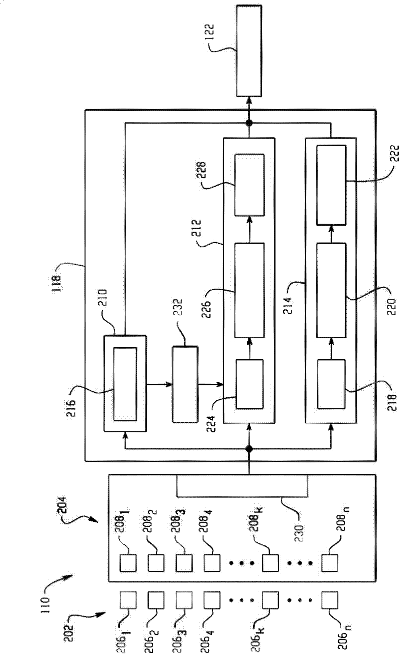
[0016] The detector array 110 subtends an angular arc opposite the examination region 108 relative to the radiation source 106 . The illustrated detector array 110 includes a two-dimensional array of detector pixels. Detector array 110 receives radiation passing through examination region 108 and generates...


PUM


Abstract

An imaging system includes a scintillator array (202) and a digital photomultiplier array (204). A photon counting channel (212), an integrating channel (210), and a moment generating channel (214) process the output signal of the digital photomultiplier array (204). A reconstructor (122) spectrally resolves the first, the second and the third output signals. In one embodiment, a controller (232) activates the photon counting channel (212) to process the digital signal only if a radiation flux is below a predetermined threshold. An imaging system includes at least one direct conversion layer (302) and at least two scintillator layers (304) and corresponding photosensors (306).; A photon counting channel (212) processes an output of the at least one direct conversion layer (302), and an integrating channel (210) and a moment generating channel (214) process respective outputs of the photosensors (306). A reconstructor (122) spectrally resolves the first, the second and the third output signals.

Description

technical field [0001] The following relates generally to spectral imaging, with specific applications in spectral computed tomography (CT). However, it can also be adapted for other medical and non-medical applications. Background technique [0002] Conventional integral computed tomography (CT) scanners typically include an x-ray tube mounted on a rotatable gantry opposite a detector array. The x-ray tube rotates around an examination region and emits multi-wavelength radiation through the examination region. The detector array receives radiation passing through the examination region and generates a signal comprising spectral information representative of the radiation. [0003] Unfortunately, in integration mode, this signal is integrated over the entire energy spectrum during each integration period, producing a signal representing the average intensity value for each integration period, and the spectral information is lost. The averaged signal is reconstructed to pr...

Claims


Application Information

Patent Timeline
Patent Type & Authority Applications(China)
IPC IPC(8): G01T1/164
CPCG01T1/2985G01T1/1647
Inventor C·博伊默C·赫尔曼R·斯特德曼W·吕腾
Owner KONINKLIJKE PHILIPS ELECTRONICS NV
Why Eureka
Try Eureka