Sheet tape-threading and locating and punching device and method

A technology for positioning punches and positioning holes, which is used in perforating tools, metal rolling, manufacturing tools, etc., and can solve the problem of the relative position of the rope hole and the reinforcing round steel being incorrect, the strip steel around the rope hole being torn, the point of force and the force Unequal problems, to avoid re-tear phenomenon, uniform force distribution, reasonable spacing

Active Publication Date: 2013-12-11
ANGANG STEEL CO LTD
View PDF7 Cites 0 Cited by
  • Summary
  • Abstract
  • Description
  • Claims
  • Application Information

AI Technical Summary

Problems solved by technology

However, the rope holes made by this method are often irregular in shape, and most of the inner walls of the rope holes have sharp corners and burrs, which lead to the threading rope being caught by the irregular holes on the wall of the rope hole during the operation of the strip steel after threading. The sharp burrs are "jammed off", causing the tape-leading operation to be interrupted
At the same time, since there are no other fixing and restraining measures, problems such as the position deviation of the rope hole and the relative position of the rope hole and the reinforced round steel are prone to occur, so that the reinforced round steel cannot bear the tension. uneven, resulting in "tearing" of the strip steel around the rope hole

Method used


Image

  • Sheet tape-threading and locating and punching device and method
  • Sheet tape-threading and locating and punching device and method
  • Sheet tape-threading and locating and punching device and method

Examples


Embodiment Construction

[0027] Below, the present invention will be further described in conjunction with the accompanying drawings.

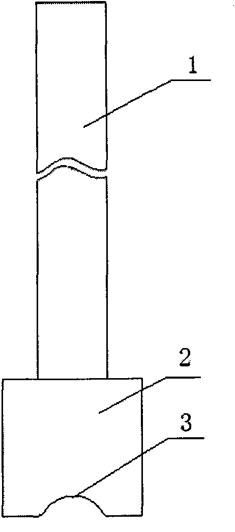
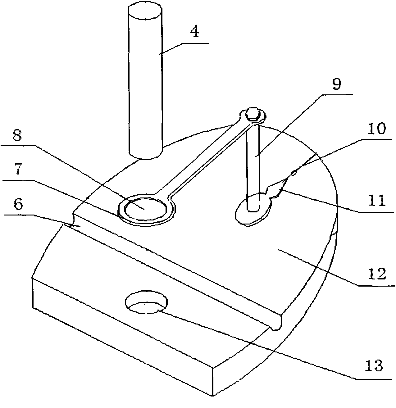
[0028] As can be seen from the accompanying drawings, the thin plate threading belt positioning punching device of the present invention is mainly composed of a stamping die, a punching chisel 4 and a positioner.

[0029] The stamping mold system is composed of an upper stamping rod 1 and a lower mold 2, that is, a stamping rod 1 is vertically welded in the middle of a cuboid mold 2, and a long arc-shaped groove 3 is processed along the lower part of the mold 2. . The mold 2 is made of 40×40×105mm square steel, and the total height of the stamping die is 200mm. The radius of the arc of the arc groove 3 is determined according to the diameter of the round steel in the punched steel sleeve, generally slightly larger than the radius of the round steel by 2mm.

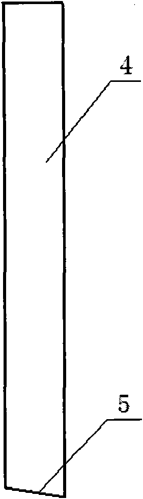
[0030] The punching chisel 4 is a cylinder, and the chisel head 5 at the lower end of the punching chisel 4 i...


PUM


Abstract

The invention provides a steel tape-threading and locating and punching device and method. The steel tape-threading and locating and punching device comprises a stamping rod, a punching chisel, and a puncher of a locator, wherein the locator comprises a base with a chisel hole and a slot, a location rotating plate with a location hole, and a pointer. A strip steel jacket arranged in the slot and provided with round steel is pressed by using a stamping die, wherein the end parts of the strip steel jacket are doubly folded, the point is aligned to a scale datum line, the punching chisel, an incline of a chisel head of which is inwards inserted in the location hole, is subjected to hammering and punching, and stamped steel reserved with a 1 / 3 connecting part is backwards coiled so that the stamped steel forms a smooth transition on the inner side of a tape-threading hole. The invention has the advantages that a space between the round steel in the steel jacket and a tape-threading rope is reasonable, the tape-threading hole is accurate in location and is uniform in stress, thus the strip steel is avoided being again torn, the defect of breaking the tape-threading rope is eliminated, and the service life of the tape-threading rope is prolonged. The steel tape-threading and locating and punching device is simple and practical, saves labor and time during punching, and has less investment and high effect taking speed because the punching device can be automatically processed and manufactured.

Description

technical field [0001] The invention belongs to the field of steel rolling aids, in particular to a positioning punching device and a positioning punching method for punching strip holes in cold-rolled thin plates. Background technique [0002] When the cold-rolled thin plate is threaded in the continuous annealing unit, in order to connect with the threading rope, the head of the strip needs to be punched out of the rope hole, so that the transmission device can pull the threading rope for leading operation. [0003] At present, the domestic conventional method of making the belt rope hole is to fold the strip steel in half first, put a reinforced round steel in the steel sleeve, and then use a flat chisel or screw rod to punch out a square or circular shape on the edge of the strip steel. rope hole. However, the rope holes made by this method are often irregular in shape, and most of the inner walls of the rope holes have sharp corners and burrs, which lead to the threadi...

Claims


Application Information

Patent Timeline
Patent Type & Authority Patents(China)
IPC IPC(8): B21B15/00B21D28/34
Inventor 付文旭
Owner ANGANG STEEL CO LTD
Why Eureka
Try Eureka