Lattice structure and lattice part

A lattice structure and lattice technology, applied in the direction of building components, etc., can solve the problems of material waste, insufficient structural high specific stiffness, high specific strength, uneven force, etc., to improve reliability, specific strength and Greater specific stiffness and reduced stress concentration

Inactive Publication Date: 2018-12-25
CENT SOUTH UNIV
View PDF4 Cites 9 Cited by
  • Summary
  • Abstract
  • Description
  • Claims
  • Application Information

AI Technical Summary

Problems solved by technology

When the existing lattice structure is stressed, the connecting rods of the lattice will be unevenly stressed. For example, under the action of bending force, the stress concentration phenomenon at the end of the connecting rod (at the node) is relatively obvious, and the node is often the first to reach Yield, structural damage often occurs near the joints, which not only causes waste of materials, but also does not give full play to the characteristics of high specific stiffness and high specific strength of the structure

Method used


Image

  • Lattice structure and lattice part
  • Lattice structure and lattice part
  • Lattice structure and lattice part

Examples


Embodiment 1

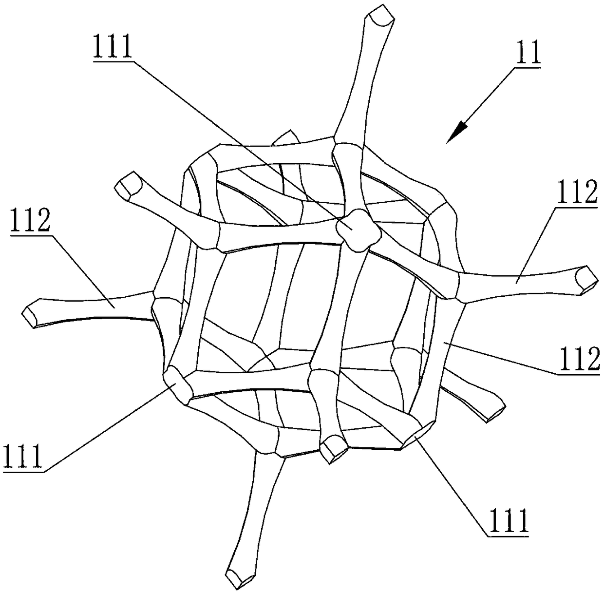
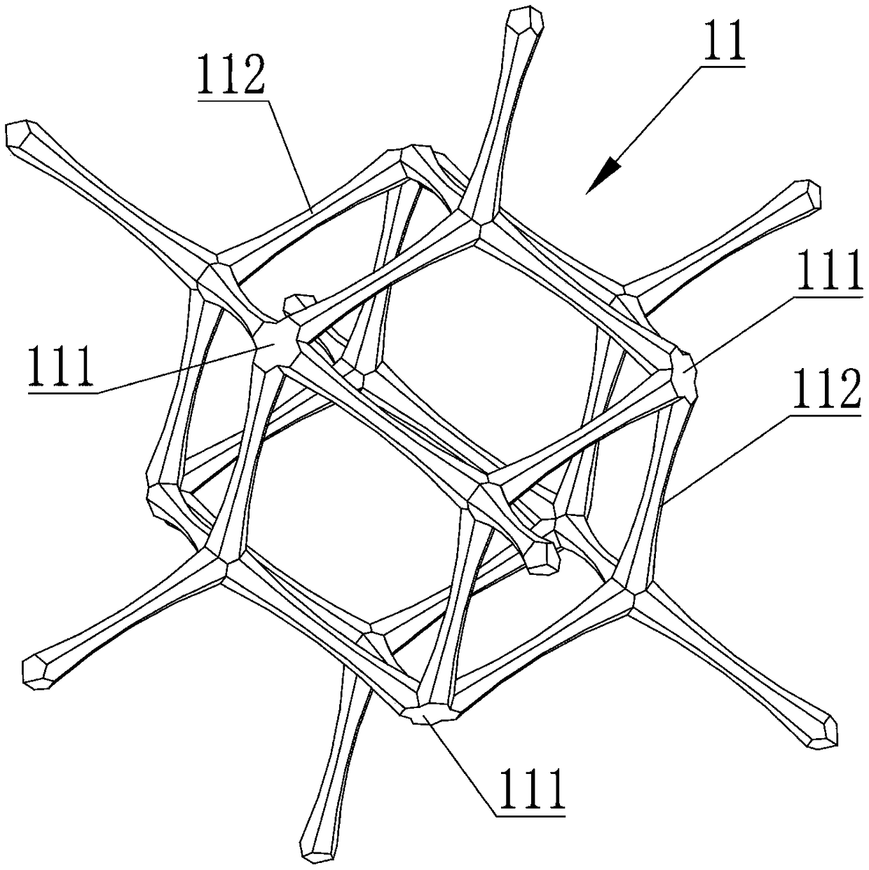
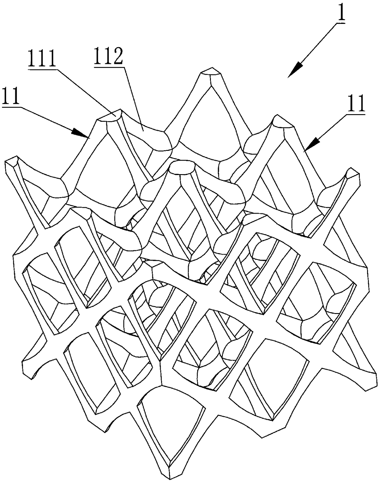
[0032] see Figure 1 to Figure 5 As shown, the lattice structure 1 provided by the embodiment of the present invention includes a plurality of lattice cells 11, and the plurality of lattice cells 11 are arranged in an array, and the array mentioned here refers to a plurality of lattice cells 11 are arranged according to certain rules, for example, by setting the number of rows, columns, and center point, the objects can be placed and arranged according to the needs. For example, in some implementations, one lattice cell 11 is used as the origin of the coordinate system, and other lattice cells 11 are arranged along the X, Y, and Z directions of the coordinate system to form a lattice structure. In some other embodiments, the lattice structure can be formed by arranging in one or two directions.

[0033] Wherein, each lattice cell 11 includes a plurality of variable-diameter connecting rods 112, and the variable-diameter side rods 112 are connected by nodes 111, that is, a cer...

Embodiment 2

[0050] The lattice structure in Embodiment 1 can be applied to many parts or material structures, for example, 3D printing fork parts, 3D printing dot matrix spherical surfaces, dot matrix interlayer materials, etc.

[0051] like Figure 9 It shows a kind of fork frame part including the lattice structure of the embodiment, the fork frame part of the fork frame part uses the lattice structure instead of the conventional structure, which reduces the weight of the fork frame, and can reduce the joints of the lattice structure nodes at the same time Stress concentration, greater specific strength and specific stiffness, improve the reliability of parts.

[0052] like Figure 10 It shows a spherical part with the lattice structure of the embodiment. The spherical part is a lattice structure as a whole instead of the conventional structure, so that the force distribution of the part can be more uniform, the stress concentration of the nodes can be reduced, and the specific strengt...


PUM


Abstract

The invention relates to the technical field of material structures, in particular to a lattice structure. The lattice structure comprises a plurality of lattice cells, wherein the plurality of lattice cells are arranged in an array; each lattice cell comprises a plurality of variable-diameter connecting rods; the variable-diameter connecting rods are connected through nodes; the diameters of twoends of the variable-diameter connecting rods are larger than that of parts between the two ends; and the diameters of the variable-diameter connecting rods are in smooth transition change. The stressdistribution of the lattice structure can be more uniform to reduce the stress concentration of nodes, and the specific strength and specific rigidity are higher. The invention also relates to a lattice part comprising the lattice structure, and the reliability of the part is improved.

Description

technical field [0001] The invention relates to the technical field of material structures, in particular to a lattice structure and lattice parts. Background technique [0002] With the rapid development of engineering technology, engineers have put forward urgent requirements for lightweight structures and diversified functions. Ultralight porous materials are a new class of multifunctional materials that have emerged with the rapid development of material preparation and machining technology in recent years, and have the remarkable characteristics of structural and functional integration. [0003] Lattice parts have high porosity, and the lattice structure can have the advantages of high specific strength, high specific stiffness and high bending strength through the unit cell configuration design of the lattice parts, so that under the same structural bearing capacity, it can save A large number of materials greatly reduce the weight of the structure. [0004] The latt...

Claims


Application Information

Patent Timeline
Patent Type & Authority Applications(China)
IPC IPC(8): F16S5/00
CPCF16S5/00
Inventor 温伟斌梁军曹晓飞
Owner CENT SOUTH UNIV
Why Eureka
Try Eureka