

Cavity gas back pressure and temperature control device
A temperature control device and gas technology, applied in the field of plastic injection molding, to achieve the effect of improving surface quality, better controlling foam size and uniformity, and better surface quality
- Summary
- Abstract
- Description
- Claims
- Application Information
AI Technical Summary
Problems solved by technology
Method used
Image

Examples
Embodiment Construction
[0039] The preferred embodiments of the present invention are described in detail as follows in conjunction with the drawings.
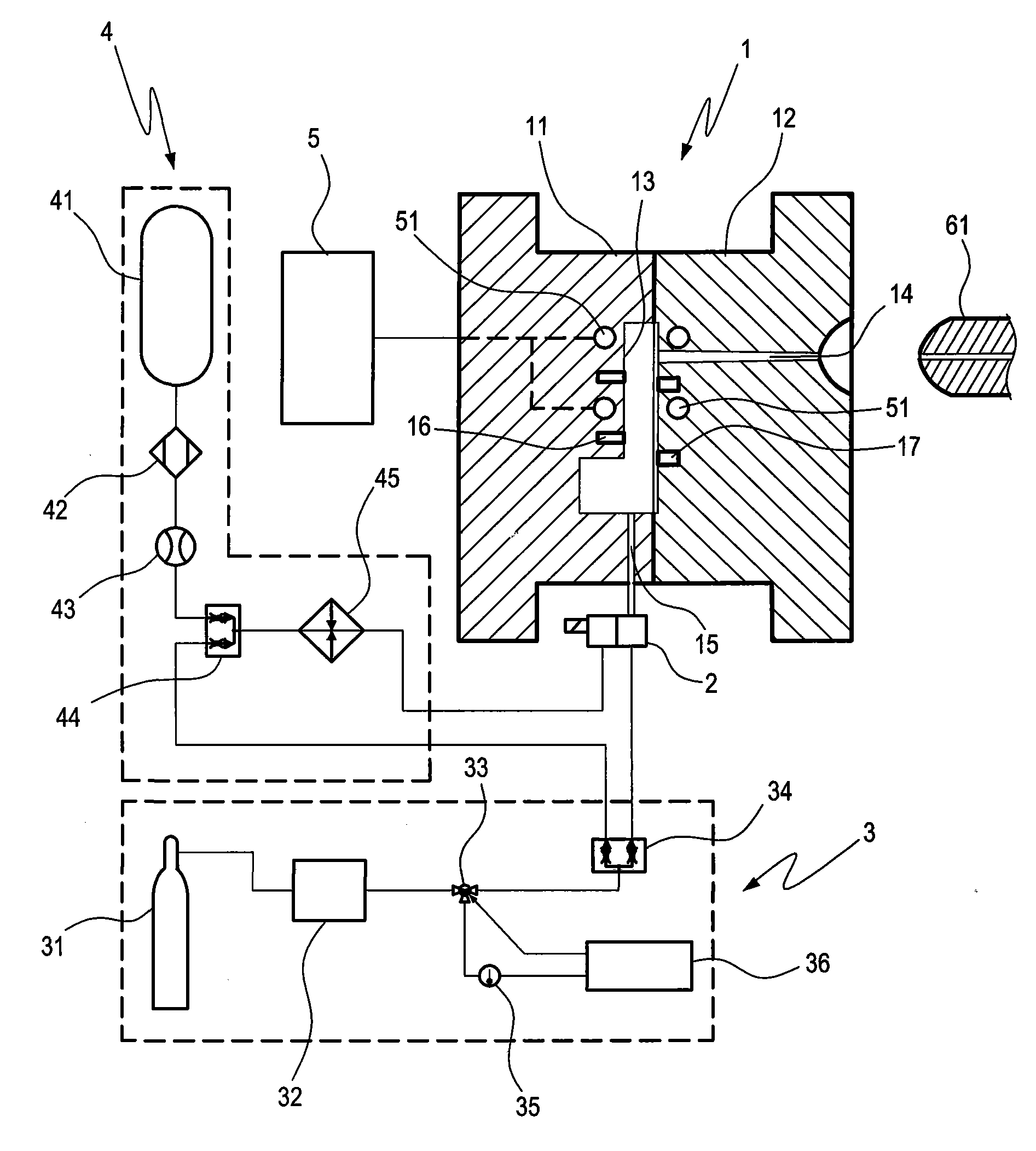
[0040] Please refer to figure 1 , which is a structural schematic diagram of the present invention.
[0041] The mold cavity gas back pressure and temperature control device of the present invention is mainly composed of a mold 1 , a program control valve 2 , a back pressure gas supply unit 3 and a high temperature gas supply unit 4 .
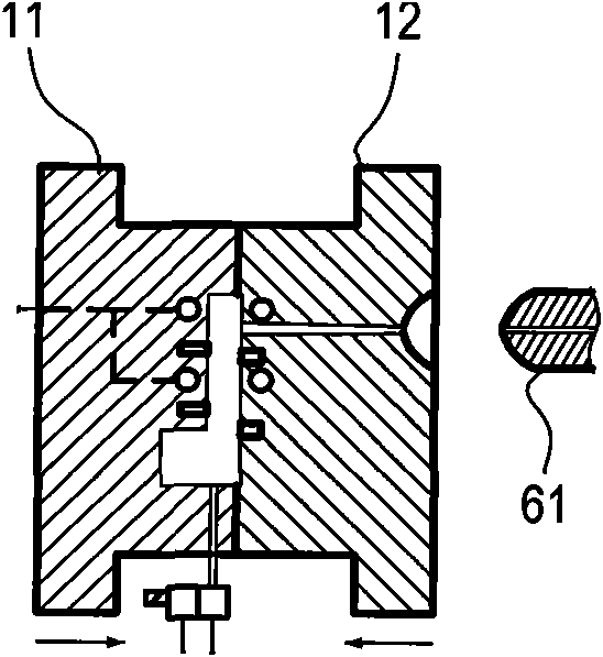
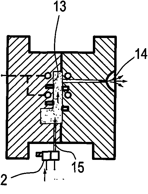
[0042] The mold 1 is composed of two half-moulds 11, 12 which can be controlled to open and close, and the two half-moulds 11, 12 are combined to form a mold cavity 13, and the mold 1 is provided with a mold cavity 13 A shot channel 14 and an air channel 15.
[0043]And the end of the injection channel 14 relative to the mold cavity can be connected or separated by the injection nozzle 61 of the injection molding machine; The control valve 2 controls the opening and closing of the air channel 15 .
[0044] The two...
PUM
 Abstract
Description
Claims
Application Information