Hydraulic circuit controlling preferred movement of moveable arm to lift or rotate

A hydraulic circuit and action technology, which is applied to mechanically driven excavators/dredgers, earth movers/shovels, construction, etc., can solve the problems of uncoordinated body rotation and slow swing of the boom, and achieve The effect of reducing energy consumption, increasing comfort and improving work efficiency

Active Publication Date: 2012-04-04
SUNWARD INTELLIGENT EQUIP CO LTD
View PDF4 Cites 27 Cited by
  • Summary
  • Abstract
  • Description
  • Claims
  • Application Information

AI Technical Summary

Problems solved by technology

Although the technical solution of this patent application solves the technical problems of the slow swing speed of the boom and the incoordination between the swing of the boom and the rotation of the body during the body rotation of the excavator, it cannot be selected under complex working conditions. Slewing priority mode, so that the two working conditions can be better coordinated, and the energy consumption of the excavator can be reduced

Method used


Image

  • Hydraulic circuit controlling preferred movement of moveable arm to lift or rotate
  • Hydraulic circuit controlling preferred movement of moveable arm to lift or rotate

Examples


Embodiment Construction

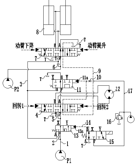
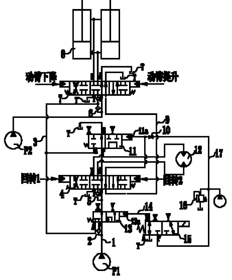
[0020] Such as figure 1 The hydraulic circuit shown to control the lift and swing priority motion of the excavator boom has:

[0021] The hydraulic actuator includes the rotary motor 12 of the rotary platform and the lifting cylinder 8 of the boom.

[0022] The hydraulic pumps include a first hydraulic pump P1 for driving the hydraulic actuator, a second hydraulic pump P2, and a pilot oil pump P3 for providing a pilot pressure oil source.

[0023] Boom control valve 7, the boom control valve 7 is installed downstream of the second hydraulic pump P2 and upstream of the boom lifting cylinder 8, the inlet P port of the boom control valve 7 is connected to the bypass oil circuit 6 with a check valve, The outlets A and B are connected to the boom lifting cylinder 8, and the control signal is the hydraulic control signal or electric control signal output by the joystick, and the control signal input from the joystick makes the spool of the boom control valve 7 switch, thereby The ...


PUM


Abstract

A hydraulic circuit controlling preferred movement of a moveable arm to lift or rotate is disclosed, and comprises a rotary motor (12), and a moveable arm lifting oil cylinder (8); a first hydraulic pump (P1), a second hydraulic pump (P2) and a guide oil pump (P3); a moveable arm control valve (7) located in the downstream of the second hydraulic pump (P2) to control hydraulic liquid which is supplied to the moveable arm lifting oil cylinder (8); a rotary control valve (4) located in the downstream of the first hydraulic pump (P1) to control the hydraulic liquid which is supplied to the rotary motor (12) and/or a confluence valve (11); a preferred valve (13) in the downstream of the first hydraulic pump (P1) for dividing the hydraulic liquid of the first hydraulic pump (P1); an electromagnetic valve (15) in the downstream of the guide oil pump (P3) for switching between the states that a guide control oil path (14) of the preferred valve (13) is communicated with the oil tank or communicated with the guide oil pump (P3); and the confluence valve (11) in the downstream of the rotary control valve (4) for controlling the oil path (1) to be communicated with the oil path (3) or an oil return pipeline.

Description

technical field [0001] The invention relates to a hydraulic circuit of a hydraulic excavator, in particular to a hydraulic circuit for controlling the lifting or rotating priority action of the arm of the excavator. Background technique [0002] The excavator is mainly composed of engine, hydraulic circuit device, working device, walking device, boarding platform and electrical control. The boom, arm and bucket of the working device are respectively supplied with oil by one pump or multiple pumps individually or jointly. The rotation of the loading platform is driven by one pump. Any two or more hydraulic actuators in the excavator simultaneously The work constitutes a compound action. In the compound action, the compound action of raising and turning the boom is a very high-frequency operating condition, and its coordination affects the working efficiency of the excavator. In the process of operation, it often happens that the boom reaches the ideal working position but th...

Claims


Application Information

Patent Timeline
Patent Type & Authority Applications(China)
IPC IPC(8): E02F9/22E02F3/43
CPCE02F3/425E02F9/123E02F9/2239E02F9/2285
Inventor 滕锦图陶海军郭勇刘均益张新海陈艳军黄兴
Owner SUNWARD INTELLIGENT EQUIP CO LTD
Why Eureka
Try Eureka