Kiln waste heat utilization system

A kiln and waste heat technology, applied in the field of calcining kilns, can solve problems such as heat source waste, and achieve the effect of reducing waste

Inactive Publication Date: 2012-04-04
张秋玲
View PDF0 Cites 0 Cited by
  • Summary
  • Abstract
  • Description
  • Claims
  • Application Information

AI Technical Summary

Problems solved by technology

[0003] Aiming at the waste of heat source caused by the direct discharge of high-temperature waste heat flue gas in traditional kilns, this invention proposes a new type of kiln waste heat utilization system, which adds a waste heat boiler device at the tail of the kiln to absorb a large amount of waste heat and generate a certain amount of waste heat. The steam is used by the user, and the waste heat flue gas after cooling is exhausted through the chimney through the induced draft fan, so as to realize energy saving and meet the energy saving and emission reduction requirements advocated by the state.

Method used


Image

  • Kiln waste heat utilization system
  • Kiln waste heat utilization system
  • Kiln waste heat utilization system

Examples


Embodiment Construction

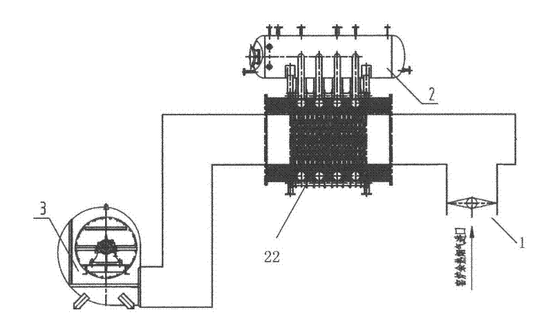
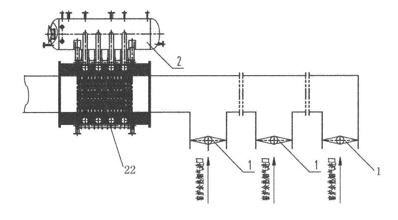
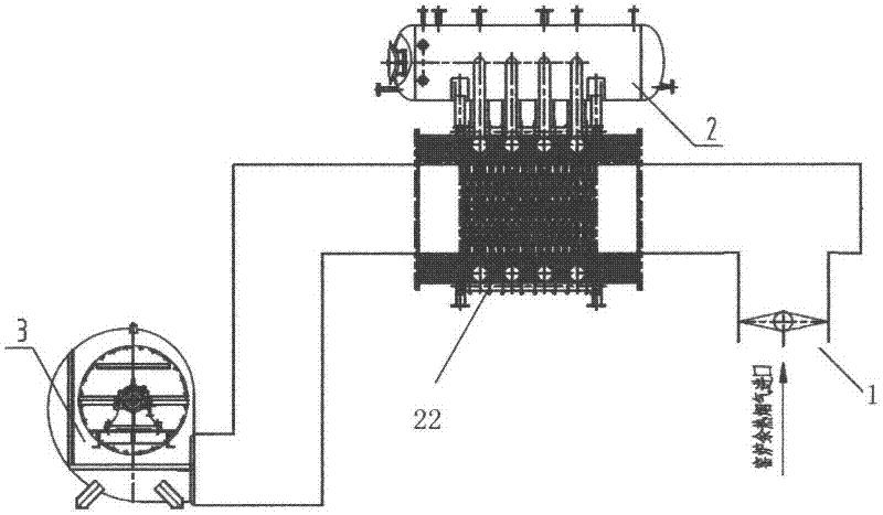
[0010] combine figure 1 Shown is a schematic diagram of the composition and structure of the kiln waste heat utilization system of the present invention. The kiln waste heat utilization system of an embodiment of the present invention includes a waste heat boiler 2 installed at the tail of the kiln. The bottom of the waste heat boiler 2 has an evaporator 22 and passes through The evaporator 22 exchanges heat with the kiln flue gas, and heats the water in the boiler to form steam for use by users; the flue gas after heat exchange is drawn out by the induced draft fan 3 to the chimney for discharge. There is a flue butterfly valve 1 at the entrance of the kiln flue gas to control the entry of flue gas. When the kiln is not working and cooling, the flue flue is closed by the flue butterfly valve 1. Described evaporator 22 selects spiral fin tube structure, and this structure is a kind of extended heating surface, under the situation of equal heating area, the steel material that ...


PUM


Abstract

The invention provides a kiln waste heat utilization system. The tail of a kiln is provided with a waste heat boiler device; the waste heat boiler exchanges heat with high temperature kiln flue gas through an evaporator consisting of spiral finned tubes; water in the boiler is heated and a certain amount of vapor is generated and used for a user; and the flue gas subjected to heat exchange and temperature reduction is extracted by a draught fan and discharged through a chimney. The kiln waste heat utilization system can generate the vapor for the user by fully utilizing the heat source of the high temperature kiln flue gas, energy waste is reduced, and an energy-saving and emission-reducing new industrial structure strongly promoted by the nation is accorded.

Description

technical field [0001] The invention relates to the technical field of calcining kilns, in particular to a kiln waste heat utilization system. Background technique [0002] A kiln is a device made of refractory materials for calcining materials or firing products. Various kilns for firing pottery, porcelain, etc. appeared in China very early. The blanks need to be calcined at high temperature in the kiln. Sintering forms the desired device. According to the variety of calcined materials, kilns can be divided into brick kilns, porcelain kilns, pottery kilns, cement kilns and other kilns. Because the firing temperature inside the kiln is very high, the high-temperature waste heat flue gas after firing in the traditional kiln is directly discharged from the chimney, which will cause a lot of waste of heat source. Contents of the invention [0003] Aiming at the waste of heat source caused by the direct discharge of high-temperature waste heat flue gas in traditional kilns, ...

Claims


Application Information

Patent Timeline
Patent Type & Authority Applications(China)
IPC IPC(8): F27D17/00F22B1/18
CPCY02P10/25
Inventor 张秋玲
Owner 张秋玲
Why Eureka
Try Eureka