Device for improving resolution of dot matrix display screen and dot matrix display screen system

A display screen and resolution technology, applied in the direction of static indicators, instruments, etc., can solve the problems of difficult production process and high cost, the occasions where close viewing cannot be used, and the practicality cannot be achieved.

Inactive Publication Date: 2012-04-04
南通惠农生物有机肥有限公司
View PDF5 Cites 9 Cited by
  • Summary
  • Abstract
  • Description
  • Claims
  • Application Information

AI Technical Summary

Problems solved by technology

[0002] Taking the LED dot matrix display as an example, large-area LED dot matrix displays are currently widely used in outdoor advertisements, stadiums and other occasions suitable for high-brightness and long-distance viewing. The rate refers to the ratio of the pixel light-emitting area to the average total area of ​​each pixel. For example, the total area of ​​each pixel of a 3mm-pitch LED screen is 3mm*3mm=9mm 2 ) and other problems, so it cannot be used in close-up viewing occasions, such as control room applications such as power dispatching and subway dispatching
LED dot matrix display manufacturers are also working hard to reduce t

Method used


Image

  • Device for improving resolution of dot matrix display screen and dot matrix display screen system
  • Device for improving resolution of dot matrix display screen and dot matrix display screen system
  • Device for improving resolution of dot matrix display screen and dot matrix display screen system

Examples


Embodiment 1

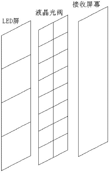
[0046] figure 2 is a schematic structural diagram of Embodiment 1 of the pixel space segmentation device of the present invention, figure 2 In the illustration, the division of sub-pixels is performed as an example by taking the pixel space division device as a controllable light valve and adopting a rectangular division method.

[0047] figure 2 In the illustration, the controllable light valve is an electronically controlled liquid crystal light valve as an example for illustration. The liquid crystal light valve is an electronically controlled liquid crystal device, which controls whether light passes or not according to the voltage applied to the liquid crystal layer.

[0048] Assuming that the original pixel size of the dot matrix display is 3 millimeters (mm), and M=K*L=4, K=L=2, then the pixel size of the liquid crystal light valve should be 1.5 mm, and every 4 liquid crystal light valves A pixel corresponds to one pixel.

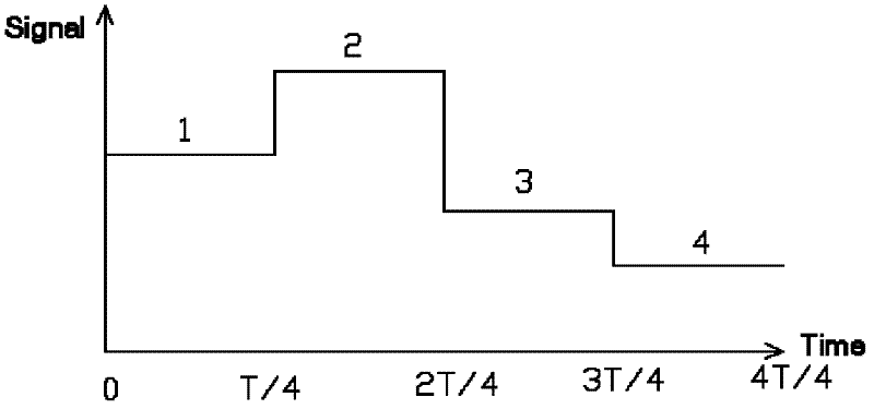
[0049] When implemented, the signal swit...

Embodiment 2

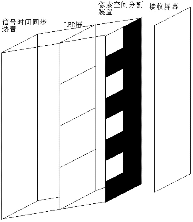
[0056] Figure 9 is a schematic structural diagram of Embodiment 2 of the pixel space segmentation device of the present invention, Figure 9 In the illustration, the division of sub-pixels is performed as an example by taking the pixel space division device as an array of apertured diaphragms and adopting rectangular division.

[0057] Figure 9 In the figure shown, the aperture diaphragm array is an array composed of a plurality of aperture diaphragms, each aperture diaphragm corresponds to each pixel, and the size of the aperture of each aperture diaphragm is smaller than the size of the pixel, and the aperture The aperture array moves according to the movement timing determined by the signal time synchronization device, so that each sub-pixel of the pixel is periodically displayed on the receiving screen.

[0058] Assuming that the size of the original pixel of the dot matrix display is 3 millimeters (mm), and M=K*L=4, K=L=2, the size of the diaphragm opening is 1 / 2 pixe...

Embodiment 3

[0066] Figure 10 It is a schematic structural diagram of Embodiment 3 of the pixel space division device of the present invention. In this embodiment, similar to the above-mentioned Embodiment 2, the pixel space division device is an aperture diaphragm array as an example for illustration, but the aperture diaphragm The structure (opening mode) of the array is different from that in the second embodiment above.

[0067] Figure 10 In the figure shown, the aperture diaphragm array is an array composed of a plurality of aperture diaphragms, each aperture diaphragm corresponds to each pixel, and the size of the aperture of each aperture diaphragm is smaller than the size of the pixel, and the aperture The aperture array moves according to the movement timing determined by the signal time synchronization device, so that each sub-pixel of the pixel is periodically displayed on the receiving screen.

[0068] Assuming that the pixel size of the dot matrix display is 3 millimeters (m...


PUM


Abstract

The invention relates to a device for improving the resolution of a dot matrix display screen and a dot matrix display screen system. The device comprises a pixel space dividing device and a signal time synchronizer, wherein the pixel space dividing device is arranged between the dot matrix display screen and a receiving screen; the signal time synchronizer is connected with the dot matrix display screen and the pixel space dividing device; and the pixel space dividing device is used for dividing each pixel of the dot matrix display screen into M sub-pixels in space according to a signal of the signal time synchronizer and periodically displaying a display image corresponding to each sub-pixel of each pixel at a corresponding position on the receiving screen. After the scheme of the invention is adopted, due to the vision persistence effect of human eyes, the display effect of dividing each original pixel into M sub-pixels can be generated so as to improve the resolution of the dot matrix display screen and enabling the dot matrix display screen to be suitable for places in which users see in a short distance in a room.

Description

technical field [0001] The invention relates to a device for improving the resolution of a dot matrix display screen and a dot matrix display screen system. Background technique [0002] Taking the LED dot matrix display as an example, large-area LED dot matrix displays are currently widely used in outdoor advertisements, stadiums and other occasions suitable for high-brightness and long-distance viewing. The rate refers to the ratio of the pixel light-emitting area to the average total area of ​​each pixel. For example, the total area of ​​each pixel of a 3mm-pitch LED screen is 3mm*3mm=9mm 2 ) and other problems, so it cannot be used in close-up viewing occasions, such as control room applications such as power dispatching and subway dispatching. LED dot matrix display manufacturers are also working hard to reduce the pixel pitch. However, with the reduction of the dot pitch, the difficulty and cost of the production process increase sharply, which cannot reach a practica...

Claims


Application Information

Patent Timeline
IPC IPC(8): G09G3/14
Inventor 黄永峰
Owner 南通惠农生物有机肥有限公司
Why Eureka
Try Eureka