
Heat exchanger structure

A technology of heat exchanger and spiral flow channel, which is applied in the field of heat exchanger structure to improve heat transfer efficiency, and can solve the problems of not showing the heat dissipation effect, discounting the water cooling function, and poor heat dissipation effect, etc.

Inactive Publication Date: 2012-04-04
ASIA VITAL COMPONENTS SHENZHEN CO LTD
View PDF10 Cites 15 Cited by
  • Summary
  • Abstract
  • Description
  • Claims
  • Application Information

AI Technical Summary

Problems solved by technology

[0004] However, although the water-cooled heat sink can improve the problem of using airflow to dissipate heat, another problem arises, that is, the end surface (that is, the heat-absorbing surface) of the water-cooled heat sink that is close to the heating component is only concentrated in the same place relationship, so that the cooling liquid in the water-cooled device only has a heat exchange effect between the lowermost fluid part and the heat-absorbing surface, while the fluid in the middle and upper layers does not produce heat exchange with the heat-absorbing surface, and the cooling liquid The time spent in the water-cooled heat sink is also too short, so that the cooling liquid has not fully absorbed enough heat (that is, heat exchange), and it is immediately and quickly led out from the aforementioned water outlet, so that the water-cooling function is greatly reduced and its heat transfer is reduced. The effect is not good, which makes the heat dissipation effect extremely inconspicuous
[0005] Because the internal flow channels of the existing water-cooled heat exchanger structure are one-way smooth flow channels, the stagnation time of the cooling liquid in these flow channels is shorter, and the heat source taken away is less. Therefore, the overall heat exchange is improved. The efficiency and heat transfer effect are obviously not good, and the heat dissipation effect is not ideal; therefore, the prior art has the following disadvantages:
[0006] 1. Poor heat exchange efficiency;
[0007] 2. Poor cooling effect

Method used


Image

  • Heat exchanger structure
  • Heat exchanger structure
  • Heat exchanger structure

Examples


Embodiment Construction

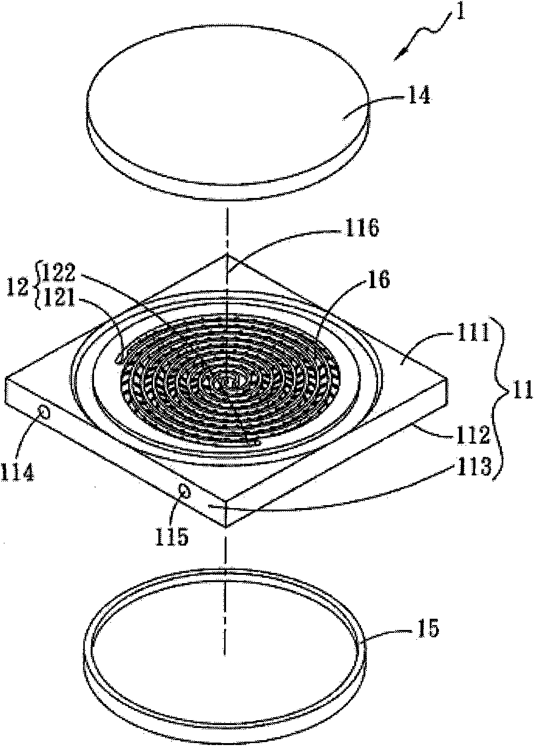
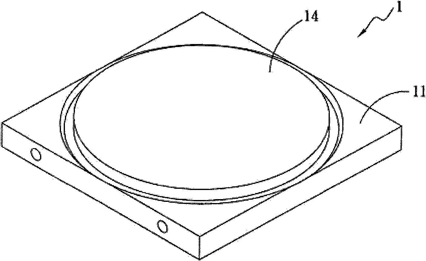
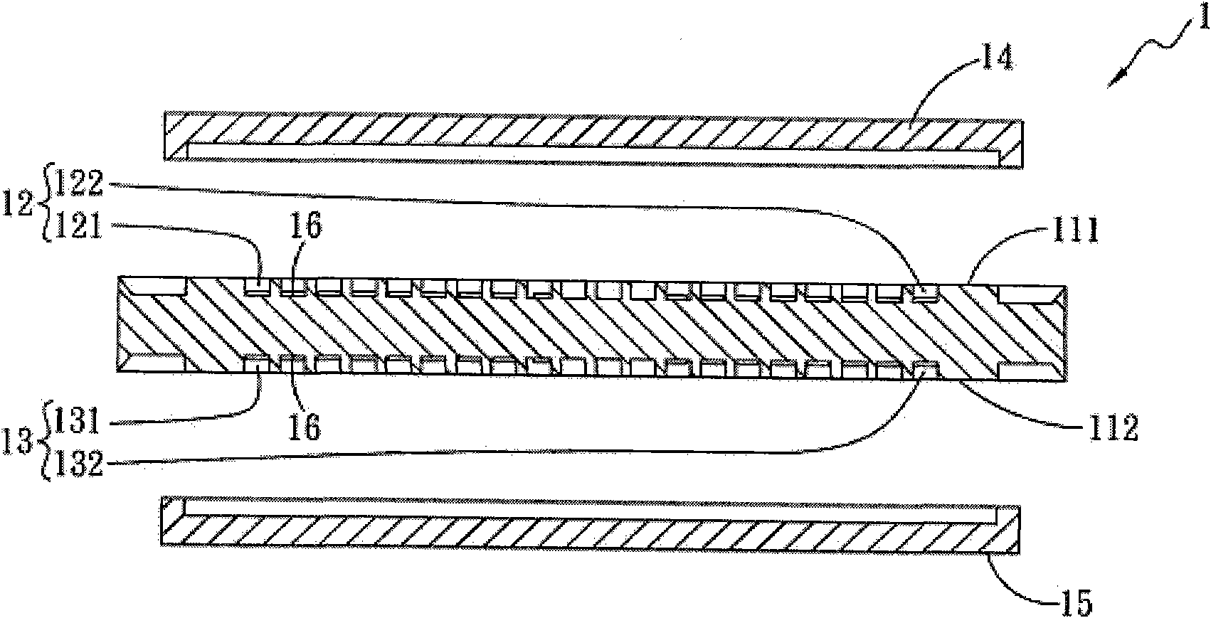
[0029] This application provides a heat exchanger structure, the diagram shows the preferred embodiment of the application, please refer to Figures 1, 2, and 3, which are three-dimensional decomposition, assembly and cross-sectional views of the first embodiment of the heat exchanger of the application. The heat exchanger 1 includes: a body 11, a first flow channel group 12, a second flow channel group 13, a first cover 14, and a second cover 15;

[0030] The main body 11 has a first side 111, a second side 112 and a third side 113, the first and second sides 111, 112 are arranged on both sides of the main body 11 correspondingly, the third side 113 and the first side The first and second sides 111 and 112 are vertically connected and provided with a water inlet 114 and a water outlet 115 .

[0031] The first flow channel group 12 is located on the first side 111 and has a first spiral flow channel 121 and a second spiral flow channel 122. The first and second spiral flow chan...


PUM


Abstract

A heat exchanger structure comprises a body. A first flow channel group and a second flow channel group are arranged on two sides of the body correspondingly and are in spiral shapes. A plurality of turbulent flow portions are arranged on one sides of the first flow channel group and the second flow channel group corresponding to the body. The body is further provided with a water inlet and a water outlet which are communicated with the first flow channel group and the second flow channel group. Fluid flows in the first flow channel group and the second flow channel group. The fluid can produce separation eddy through the turbulent flow portions so as to greatly improve turbulence intensity of a flow field to improve heat transfer efficiency.

Description

technical field [0001] The invention relates to a heat exchanger, in particular to a heat exchanger structure for improving heat transfer efficiency. Background technique [0002] With the advancement of electronic information technology, the use of electronic equipment (such as computers, notebook computers, communication chassis...etc.) Waste heat will be generated. If the above-mentioned waste heat cannot be discharged from the electronic equipment in time, it is very easy to accumulate the waste heat in the electronic equipment, causing the temperature inside the electronic equipment and the electronic components inside the electronic equipment to continue to rise, which will cause the electronic components to fail due to overheating , damage or reduced operating efficiency. [0003] In order to improve the above-mentioned heat dissipation problem in the prior art, it is generally more common to install a heat dissipation fan in the electronic equipment to force heat di...

Claims


Application Information

Patent Timeline
IPC IPC(8): H05K7/20H01L23/473F28F9/24
Inventor 罗世平张立东阮伟诚
Owner ASIA VITAL COMPONENTS SHENZHEN CO LTD
Learn More