Novel mechanical supercharger structure and electromagnetic clutch mechanism applied to same

A supercharger, electromagnetic clutch technology, applied in non-mechanical drive clutches, machines/engines, magnetic drive clutches, etc., can solve the problem of limited improvement in engine power and torque, deterioration of engine fuel economy, and difficulty in mechanical superchargers. Matching and other issues to achieve the effect of reducing energy, achieving high-efficiency work, and real-time effective input

Active Publication Date: 2013-08-07
JAPHL POWERTRAIN SYST
View PDF6 Cites 0 Cited by
  • Summary
  • Abstract
  • Description
  • Claims
  • Application Information

AI Technical Summary

Problems solved by technology

The engine requires little power under idling or low-load conditions. The traditional supercharger connected to the engine pulley with a fixed transmission ratio has been supercharging the engine, and the supercharger itself consumes power, so this The fuel economy of the engine is poor
In addition, the ratio of the speed of the traditional supercharger to the speed of the engine is fixed. When the engine is running at a low speed, such as around 1500rpm, the speed of the supercharger is low. At this time, the supercharger has no supercharging effect on the engine. Obvious, so engine power and torque gains are limited
And when the engine is running at high speed, such as around 4500rpm, although the supercharger running at high speed provides a large boost pressure for the engine, it consumes more engine power at the same time, which worsens the engine's performance. Fuel economy, so it is difficult for a traditional supercharger to match the engine well in the full operating range of the engine

Method used


Image

  • Novel mechanical supercharger structure and electromagnetic clutch mechanism applied to same
  • Novel mechanical supercharger structure and electromagnetic clutch mechanism applied to same
  • Novel mechanical supercharger structure and electromagnetic clutch mechanism applied to same

Examples


Embodiment Construction

[0022] Below with reference to the accompanying drawings, through the description of the embodiments, the specific embodiments of the present invention, such as the shape, structure, mutual position and connection relationship between the various parts, the role and working principle of the various parts, etc., will be further described. Detailed instructions:

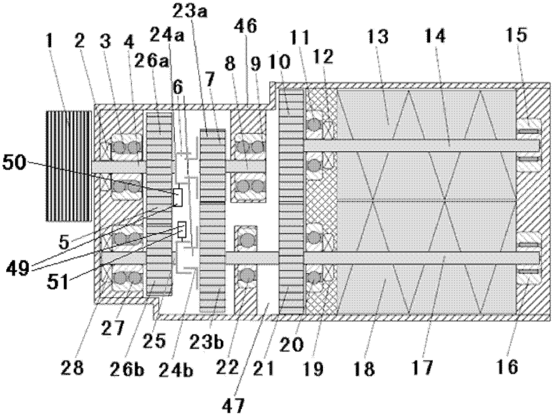
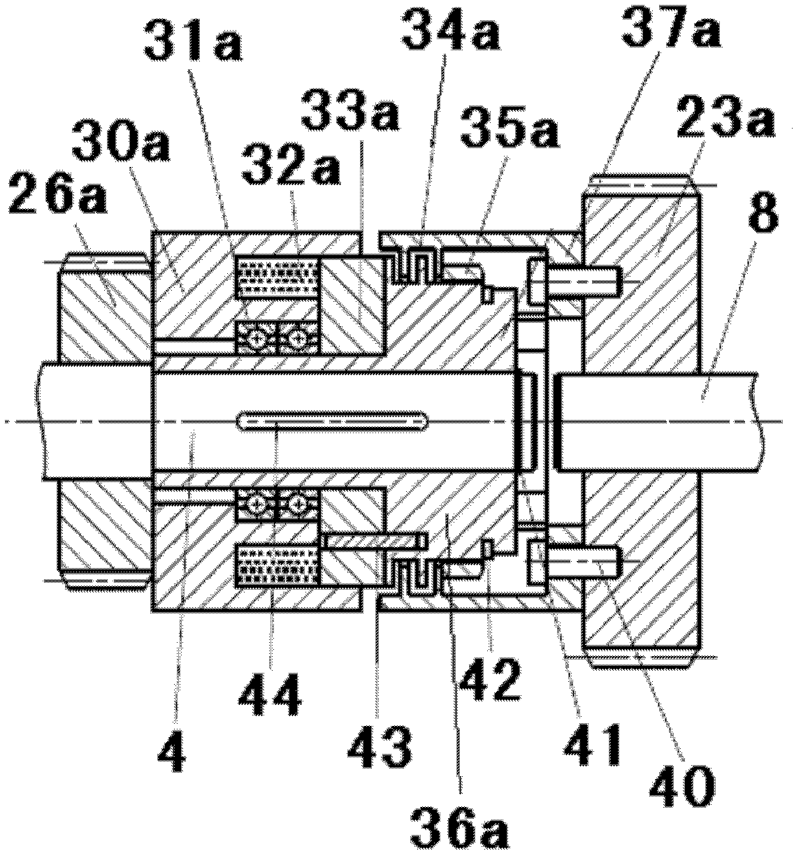
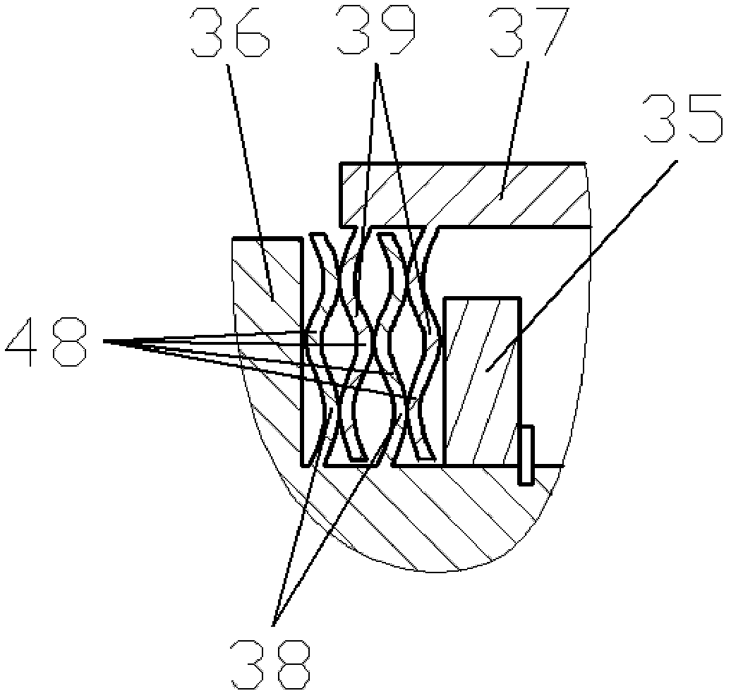
[0023] as attached figure 1 — attached image 3 As shown, the present invention is a novel mechanical supercharger structure, comprising a supercharger housing 46, an input shaft 4, a sealed oil chamber 47 is arranged in the supercharger housing 46, and one end of the input shaft 4 is connected to the pulley 1 Connected, the other end extends into the supercharger housing 46, the input shaft 4 that extends into the supercharger housing 46 is installed at one end with a gear 5, and the speed regulating gear 7 is also arranged in the oil chamber 47, the described An electromagnetic clutch 6 capable of controlling the c...


PUM


Abstract

The invention provides a novel mechanical supercharger structure applied to the technical field of superchargers and also relates to an electromagnetic clutch mechanism applied to the mechanical supercharger structure. The novel mechanical supercharger structure comprises a supercharger shell (46) and an input shaft (4), wherein a sealed oil chamber (47) is arranged in the supercharger shell (46); one end of the input shaft (4) is connected with a belt pulley (1), and the other end of the input shaft (4) extends into the supercharger shell (46); a gear (5) is installed at one end of the inputshaft (4) extending into the supercharger shell (46); a governor gear (10) is also arranged in the oil chamber (47); and an electromagnetic clutch (6) capable of controlling the clutching of the gear(5) and a governor gear (7) is installed on the gear (5) and is connected with an ECU (Engine Control Unit) for controlling work of the electromagnetic clutch (6). According to the novel mechanical supercharger structure disclosed by the invention, the flexible speed change of the supercharger can be realized; and the reliability and the durability of the supercharger are improved.

Description

technical field [0001] The invention belongs to the technical field of superchargers, and more specifically relates to a new structure of a supercharger. The invention also relates to an electromagnetic clutch mechanism applied to the structure of a supercharger. Background technique [0002] A supercharger, especially a Roots-type supercharger, is a commonly used supercharging method for engines. The Roots-type supercharger is a volumetric compressor, which is driven by the engine pulley with a fixed transmission ratio, and its exhaust flow is basically linear in relation to its speed. As an important component of a supercharged engine, the flow rate and boost pressure of the supercharger not only directly affect the output power, torque and fuel consumption of the engine, but also affect the acceleration, comfort and reliability of the assembled vehicle. Compared with an engine equipped with a turbocharger, a supercharger engine can obtain better throttle response. The hi...

Claims


Application Information

Patent Timeline
Patent Type & Authority Patents(China)
IPC IPC(8): F02B39/04F02B39/12F16D27/02
Inventor 马丽施法佳范礼姜倩周俊
Owner JAPHL POWERTRAIN SYST
Why Eureka
Try Eureka